00198711-01_UM_X-Serie-S_EN.pdf - 第119页
Instruction manual SIPLACE X-Series 3 Technical data and assemblies From software version 713.0 Edition 11/2019 3.5 Placement head 119 3.5.2 SIPLACE SpeedS tar C&P20 P2 The SIPLACE X-Series S uses the SIPLACE Sp eedS…
3 Technical data and assemblies Instruction manual SIPLACE X-Series
3.5 Placement head From software version 713.0 Edition 11/2019
118
3.5.1.2 Technical data SIPLACE SpeedStar (C&P20 P)
3
SIPLACE SpeedStar (C&P20 P)
With component camera type
23
With component camera type
41
Component range
*a
01005 to 2220, Melf, SOT, SOD 0201 (metric) to 2220, Melf, SOT,
SOD, Bare-Die, Flip-Chip
Component spec.
Max. height
Min. lead pitch
Min. lead width
Min. ball pitch
Min. ball diameter
Min. dimensions
Max. dimensions
Max. weight
4 mm
250 µm
100 µm
400 µm
200 µm
0.18 mm x 0.18 mm
6 mm x 6 mm
1 g
4 mm
80 µm
30 µm
100 µm
50 µm
0.12 mm x 0.12 mm
6 mm x 6 mm
1 g
Set-down force Touchless Placement, 1.3 N ± 0.5 N (standard)
0.5 N - 4.5 N
Nozzle types 40xx 40xx
X/Y accuracy
*b
± 36 µm/3σ ± 36 µm/3σ
Angular accuracy ± 0.5° / 3σ ± 0.5° / 3σ
Illumination level 5 5
Possible illumination level settings 256
5
256
5
*)a Please note that the placeable component range is also affected by the pad geometry, the customer-specific standards,
the component packaging tolerances and the component tolerances.
*)b The accuracy values fulfill the conditions in the SIPLACE scope of supply and services.

Instruction manual SIPLACE X-Series 3 Technical data and assemblies
From software version 713.0 Edition 11/2019 3.5 Placement head
119
3.5.2 SIPLACE SpeedStar C&P20 P2
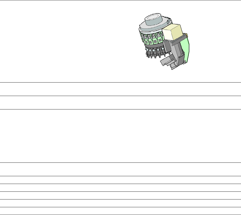
The SIPLACE X-Series S uses the SIPLACE SpeedStar C&P20 P2 for top placement perfor-
mance.
3
CAUTION
Always take hold of the handle to push the placement head
The placement head may only be moved by pushing manually against the handle provid-
ed.
3 Technical data and assemblies Instruction manual SIPLACE X-Series
3.5 Placement head From software version 713.0 Edition 11/2019
120
3.5.2.1 Overview
3
3
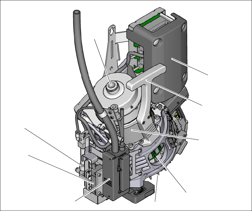
Fig. 3.5 - 2 SIPLACE SpeedStar - overview
(1) Connection for the holding circuit of the vacuum pump
(2) "Intermediate distributor" board (under the cover)
(3) Handle
(4) Star motor
(5) DP drive
(6) Nozzle
(7) Pressure control valve
(8) Z motor (linear motor)
(9) Return cylinder
(5)
(1)
(7)
(2)
(3)
(4)
(6)
(8)
(9)