00198711-01_UM_X-Serie-S_EN.pdf - 第126页
3 Technical data and assemblies Instruction manual SIPLACE X-Series 3.5 Placement head From software version 713.0 Edition 11/2019 126 3 Fig. 3.5 - 6 SIPLACE MultiSt ar CPP - fr ont view , function groups part 2 (1) C&am…
Instruction manual SIPLACE X-Series 3 Technical data and assemblies
From software version 713.0 Edition 11/2019 3.5 Placement head
125
3.5.5 SIPLACE MultiStar CPP
3
3
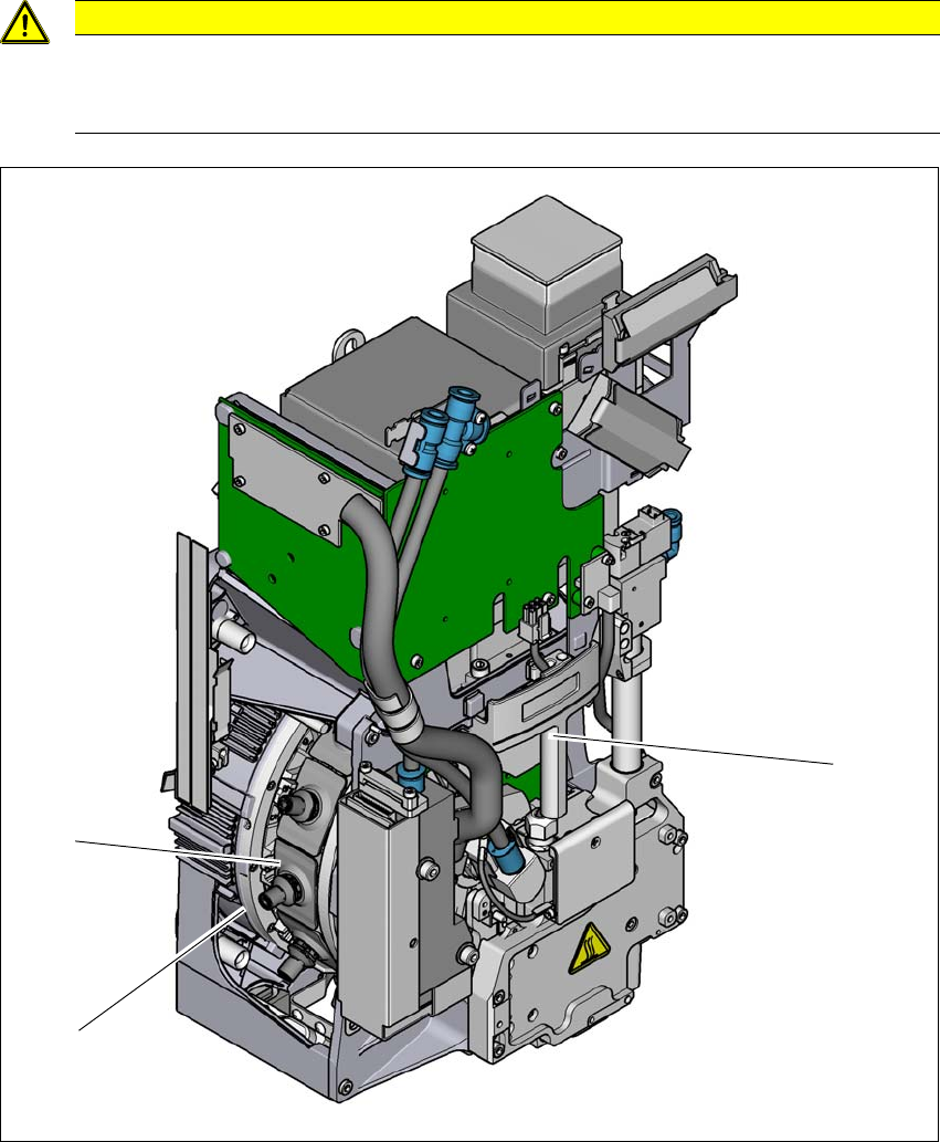
Fig. 3.5 - 5 SIPLACE MultiStar CPP - front view, function groups part 1
(1) Handle
(2) Star with 12 segments
(3) Segment with integrated DP drive
CAUTION
Always take hold of the handle to push the placement head
The placement head may only be moved by pushing manually against the handle provid-
ed.
(2)
(3)
(1)
3 Technical data and assemblies Instruction manual SIPLACE X-Series
3.5 Placement head From software version 713.0 Edition 11/2019
126
3
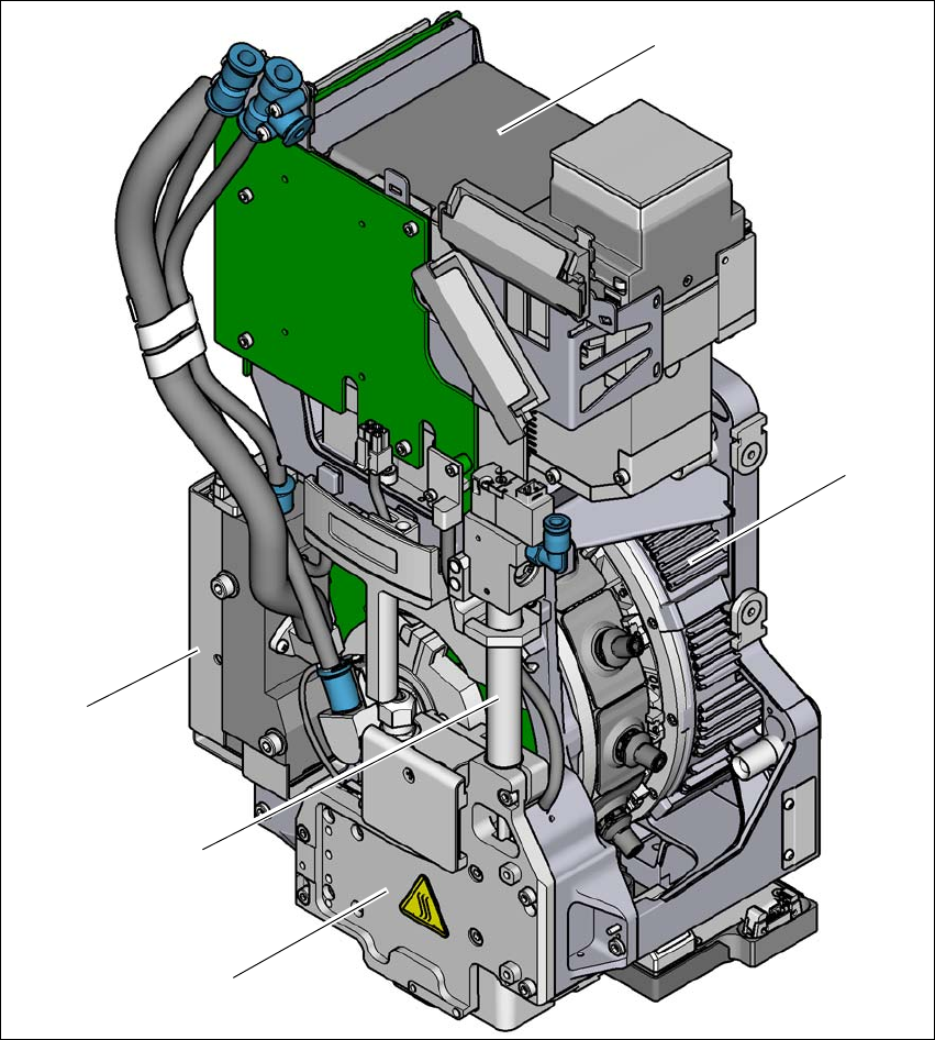
Fig. 3.5 - 6 SIPLACE MultiStar CPP - front view, function groups part 2
(1) C&P component camera, type 30 GigE
(2) Torque motor for star drive
(3) Z drive (linear motor)
(4) Return cylinder
(5) Pressure control valve
(1)
(2)
(3)
(4)
(5)
Instruction manual SIPLACE X-Series 3 Technical data and assemblies
From software version 713.0 Edition 11/2019 3.5 Placement head
127
3
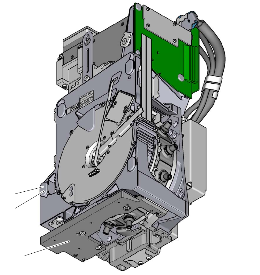
Fig. 3.5 - 7 SIPLACE MultiStar CPP - back view, function groups part 3
(1) Component sensor
(2) Assembly position for component height of up to 11.5 mm
(3) Assembly position for component height of up to 6 mm
3.5.5.1 Assembly positions of SIPLACE MultiStar CPP
The SIPLACE MultiStar CPP head can be fitted to the head mount in two different positions:
– SIPLACE MultiStar CPP in the top assembly position
In this position, all components can be processed up to a size of 50 mm x 40 mm and a height
of 15.5 mm. 3
(3)
(2)
(1)