00198711-01_UM_X-Serie-S_EN.pdf - 第133页
Instruction manual SIPLACE X-Series 3 Technical data and assemblies From software version 713.0 Edition 11/2019 3.5 Placement head 133 3.5.5.8 T echnical data for SIPLACE MultiS tar (CPP) 3 SIPLACE MultiStar (CPP) with c…

3 Technical data and assemblies Instruction manual SIPLACE X-Series
3.5 Placement head From software version 713.0 Edition 11/2019
132
3.5.5.7 SIPLACE MultiStar CPP in advanced Pick&Place mode with limited rotation
The SIPLACE MultiStar CPP can place the entire component spectrum from 01005 to 50 mm
x 40 mm in this mode. The large components are picked up last, optically centered and then
placed as first components.
3
Fig. 3.5 - 10 SIPLACE MultiStar CPP - mixed mode
K_BE Small component (see table 3.5 - 1, page 128)
M_BE_2 Medium sized component, type 2 (see table 3.5 - 1
, page 128)
G_BE Large component (see table 3.5 - 1
, page 128)
Type 30 Component camera, type 30
Type 33 Stationary component camera, type 33
1 ... 8 Order of components taken up
3
Neighboring segments of the SIPLACE MultiStar CPP head are not able to take up components
of types M_BE_2 and G_BE if the diagonal length of these components is longer than 39.8 mm.
Type 30
K_BE
G_BE
Type 33
M_BE_2
Instruction manual SIPLACE X-Series 3 Technical data and assemblies
From software version 713.0 Edition 11/2019 3.5 Placement head
133
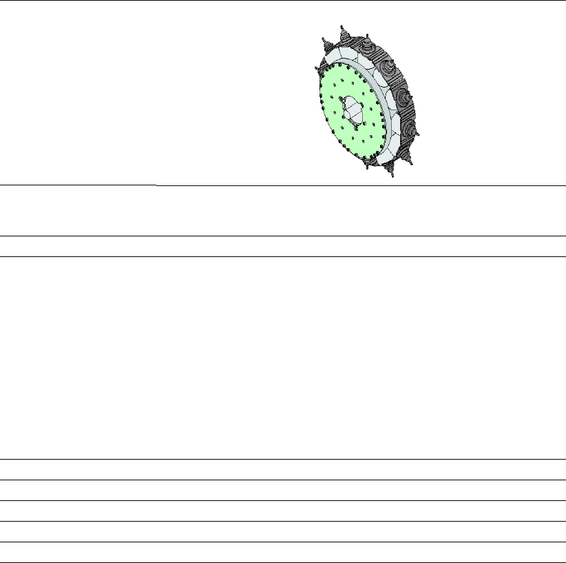
3.5.5.8 Technical data for SIPLACE MultiStar (CPP)
3
SIPLACE MultiStar (CPP)
with component camera type 30 with component camera type
33
(stationary camera)
Component range
*a
*)a Please note that the placeable component range is also affected by the pad geometry, the customer-
specific standards, the component packaging tolerances and the component tolerances.
01005 to 27 mm x 27 mm 0402 to 50 mm x 40 mm
*b
*)b A diagonal of 69 mm is possible during multiple measurements (e.g. 60 mm x 10 mm).
Component spec.
Max height
*c
Max. height
*d
Min. lead pitch
Min. lead width
Min. ball pitch
Min. ball diameter
Min. dimensions
Max. dimensions
Max. weight
*)c CPP head: In low installation position (stationary component camera not possible).
*)d CPP head: In high installation position
6.0 mm
8.5 mm
250 µm
100 µm
*e
/ 200 µm
*f
250 µm*
e
/ 350 µm
140 µm*
e
/ 200 µm
f
0.4 mm x 0.2 mm
27 mm x 27 mm
4 g
20 g in Pick&Place mode
*)e For components < 18 mm x 18 mm.
*)f For components ≥ 18 mm x18 mm.
15.5 mm
*g
300 µm
150 µm
350 µm
200 µm
1.0 mm x 0.5 mm
50 mm x 40 mm
8 g
20 g in Pick&Place mode
*)g With OSC package
Set-down force 1.0 - 15 N*
g
1.0 - 15 N*
g
Nozzle types 20xx, 28xx 20xx, 28xx
X/Y accuracy
*h
*)h The accuracy values fulfill the conditions in the SIPLACE scope of supply and services.
± 41 µm/3σ ± 34 µm/3σ
Angular accuracy ± 0.20° / 3σ
*i
, ± 0.38° / 3σ
*j
*)i Component dimensions between 6 mm x 6 mm and 27 mm x 27 mm.
*)j Component dimensions smaller than 6 mm x 6 mm.
± 0.14° / 3σ
Illumination level 5 6
3 Technical data and assemblies Instruction manual SIPLACE X-Series
3.5 Placement head From software version 713.0 Edition 11/2019
134
3.5.6 SIPLACE TwinStar for high precision IC placement
3
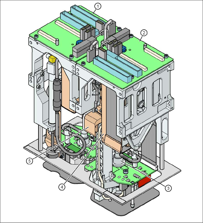
Fig. 3.5 - 11 SIPLACE TwinStar for high precision IC placement
3
(1) Pick&Place module 1 (P&P1) - the TwinStar consists of 2 Pick&Place modules
(2) Pick&Place module 2 (P&P2)
(3) DP axis
(4) Z axis drive
(5) Incremental distance measuring system for the Z axis