00198711-01_UM_X-Serie-S_EN.pdf - 第136页
3 Technical data and assemblies Instruction manual SIPLACE X-Series 3.6 Gantry system From software version 713.0 Edition 11/2019 136 3.6 Gantry system 3.6.1 Position of gant ries in SIPLACE X4i S 3 Fig. 3.6 - 1 Position…
Instruction manual SIPLACE X-Series 3 Technical data and assemblies
From software version 713.0 Edition 11/2019 3.5 Placement head
135
3.5.6.1 Technical data Twin Star
SIPLACE TwinStar
with component camera type 33
(fine pitch camera)
with component camera type 25
(flip chip camera)
Component range
*a
0402 to SO, PLCC, QFP, BGA, special
components, bare dies, flip-chips
0201 to SO, PLCC, QFP, sockets,
plugs, BGA, special components, bare
dies, flip-chips, shields
Component specs
*b
Max. height
Min. lead pitch
Min. lead width
Min. ball pitch
Min. ball diameter
Min. dimensions
Max. dimensions
Max. weight
*c
25 mm (higher available on request)
300 µm
150 µm
350 µm
200 µm
1.0mm x 0.5mm
55 mm x 45 mm (single measurement)
Up to
200 mm x 125 mm (multiple measure-
ment)
*d
160 g
25 mm (higher available on request)
250 µm
100 µm
140 µm
80 µm
0.6mm x 0.3mm
16 mm x 16 mm (single measurement)
160 g
Set-down force
Standard
With OSC package
1.0 N - 15 N
2.0 N - 30 N
1.0 N - 15 N
2.0 N - 30 N
Nozzle types
*e
5xx (standard)
20xx/28xx + adapter
4xx + adapter
9xx + adapter
gripper
5xx (standard)
20xx/28xx + adapter
4xx + adapter
9xx + adapter
gripper
Nozzle spacing for P&P
heads
70.8 mm 70.8 mm
X/Y accuracy
*f
± 28 µm/3σ ± 22 µm/3σ
Angular accuracy ± 0.05° / 3σ, ± 0.05° / 3σ
Illumination level 6 6
*)a Please note that the placeable component range is also affected by the pad geometry, the customer-specific standards,
the component packaging tolerances and the component tolerances.
*)b If the MultiStar and TwinStar are combined in the same placement area, the maximum component height may be re-
stricted .
*)c If standard nozzles are used
*)d Depending on the component dimensions and component infeed, other restrictions may also apply, which SIPLACE Pro
will automatically take into account.
*)e Over 300 different nozzles and 100 gripper types are available, with an extensive nozzle database available online.
*)f The accuracy values fulfill the conditions in the SIPLACE scope of supply and services.
3 Technical data and assemblies Instruction manual SIPLACE X-Series
3.6 Gantry system From software version 713.0 Edition 11/2019
136
3.6 Gantry system
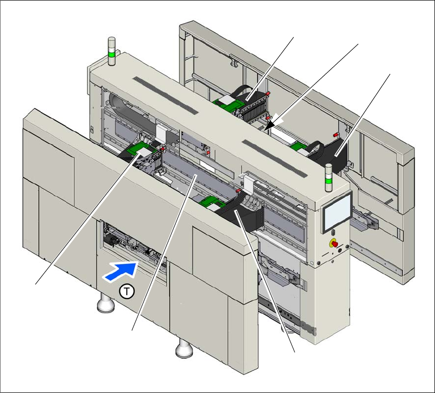
3.6.1 Position of gantries in SIPLACE X4i S
3
Fig. 3.6 - 1 Position of gantries - SIPLACE X4i S
(1) Y axis, gantry 1 and gantry 4
(2) X axis, gantry 1
(3) X axis, gantry 2
(4) Y axis, gantry 3 and gantry 4 (concealed)
(5) X axis, gantry 3
(6) X axis, gantry 4
(T) Direction of PCB transport
(1)
(3)
(6)
(4)
(2)
(5)
Instruction manual SIPLACE X-Series 3 Technical data and assemblies
From software version 713.0 Edition 11/2019 3.6 Gantry system
137
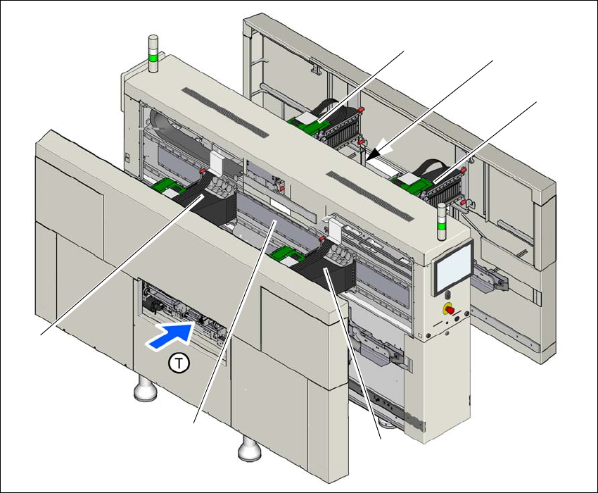
3.6.2 Position of gantries in SIPLACE X4 S
3
Fig. 3.6 - 2 Position of gantries - SIPLACE X4 S
(1) Y axis, gantry 1 and gantry 4
(2) X axis, gantry 1
(3) X axis, gantry 2
(4) Y axis, gantry 3 and gantry 4 (concealed)
(5) X axis, gantry 3
(6) X axis, gantry 4
(T) Direction of PCB transport
(1)
(3)
(6)
(4)
(2)
(5)