00198711-01_UM_X-Serie-S_EN.pdf - 第170页
3 Technical data and assemblies Instruction manual SIPLACE X-Series 3.9 Component trolley From softwa re version 713.0 Edition 11/2019 170 3.9 Component trolley Item no. 001 1972 2-xx SIPLACE X-S eries S comp onent troll…
Instruction manual SIPLACE X-Series 3 Technical data and assemblies
From software version 713.0 Edition 11/2019 3.8 SIPLACE tape feeder modules for SIPLACE X-Series S
169
3
3
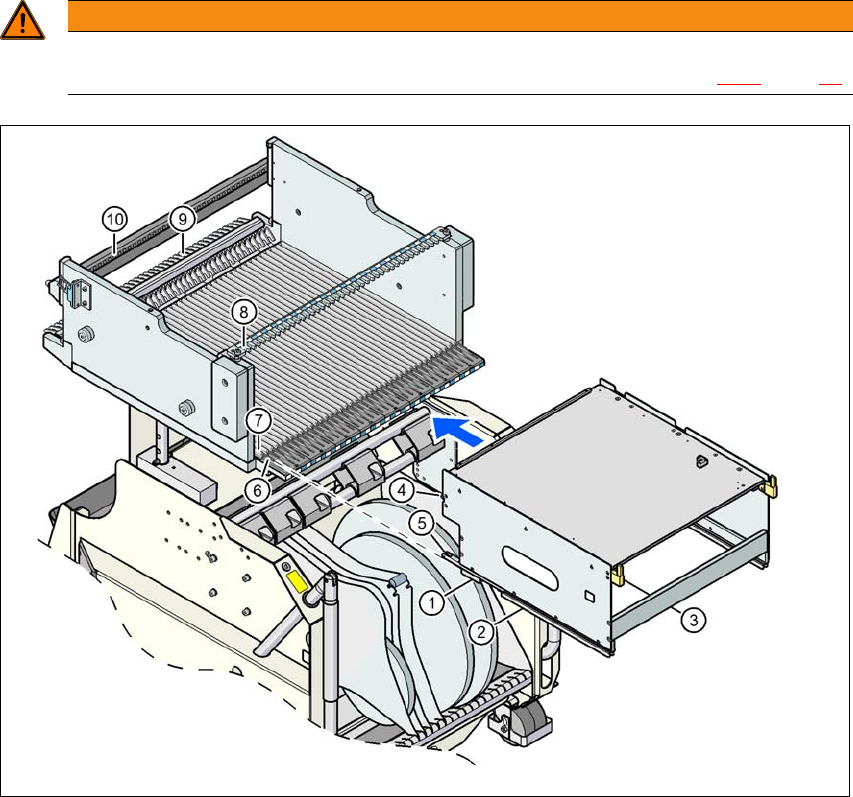
Fig. 3.8 - 11 Using a waffle pack tray holder on the X-Series S component trolley
WARNING
Occupation of locations!
Always follow the safety instructions about occupying locations, in section 2.6.5
, page 88.
(1) Front slider guide (6) Insertion aid
(2) Back slider guide (7) Sliding rail (omega profile)
(3) "Back" centering pin (8) Recesses in the centering bar for holding the
"back" centering pin
(4) "Front" centering pin (9) Locking latches
(5) Locking roller (10) Centering holes on the changeover table for
holding the "front" centering pin
3 Technical data and assemblies Instruction manual SIPLACE X-Series
3.9 Component trolley From software version 713.0 Edition 11/2019
170
3.9 Component trolley
Item no. 00119722-xx SIPLACE X-Series S component trolley
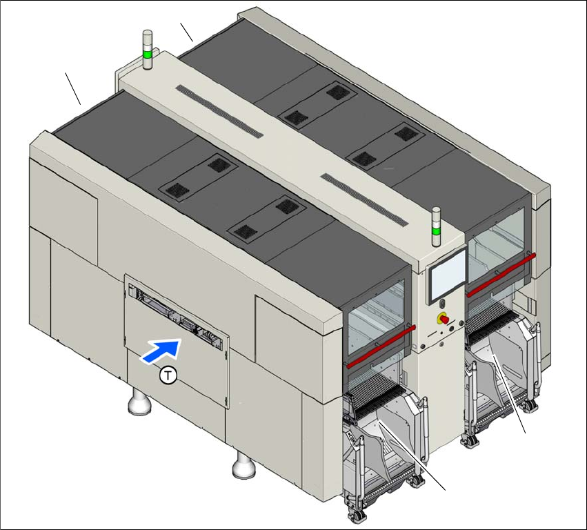
Four SIPLACE X-Series S component trolleys can be docked onto SIPLACE X-Series S place-
ment machines.
3
Fig. 3.9 - 1 Component trolley locations (example of SIPLACE X4i S shown)
(1) Location 1
(2) Location 2
(3) Location 3
(4) Location 4
(T) Direction of PCB transport
The component trolleys are stand-alone modules that can be set up with feeders at an external
setup area. This means that the production process only has to be interrupted briefly in order to
change the component trolley.
(1)
(4)
(2)
(3)
Instruction manual SIPLACE X-Series 3 Technical data and assemblies
From software version 713.0 Edition 11/2019 3.9 Component trolley
171
3
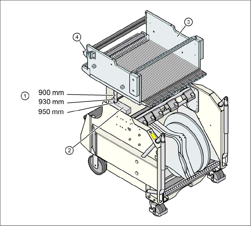
Fig. 3.9 - 2 Component trolley, SIPLACE X-Series S, with a PCB conveyor height of 950 mm
3
(1) Holes in the guide columns for the transport heights of 900, 930 and 950 mm.
(2) Support block
(3) Changeover table
(4) Contact for switching the safety switch in the COT insert