00198711-01_UM_X-Serie-S_EN.pdf - 第181页
Instruction manual SIPLACE X-Series 3 Technical data and assemblies From software version 713.0 Edition 11/2019 3.9 Component tr olley 181 3.9.8.2 Maximum t ape reel diameter in relation to the PCB conveyor height 3 3 3.…
3 Technical data and assemblies Instruction manual SIPLACE X-Series
3.9 Component trolley From software version 713.0 Edition 11/2019
180
3.9.8 SIPLACE X-Series S tape container
3.9.8.1 Description
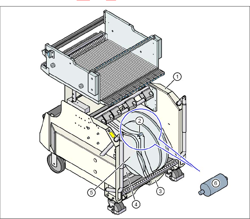
The tape container can hold reels up to 19" (483 mm) in diameter. The insertion of separating
plates is described in section 5.9.5
page 263.
3
Fig. 3.9 - 9 SIPLACE X-Series S component trolley, with tape container
(1) Component trolley
(2) Position of spindles
(3) Waste tape container
(4) Tape container
(5) Separating plate
(6) Spindle (zoom)
Instruction manual SIPLACE X-Series 3 Technical data and assemblies
From software version 713.0 Edition 11/2019 3.9 Component trolley
181
3.9.8.2 Maximum tape reel diameter in relation to the PCB conveyor height
3
3
3.9.9 Used tape chute
3
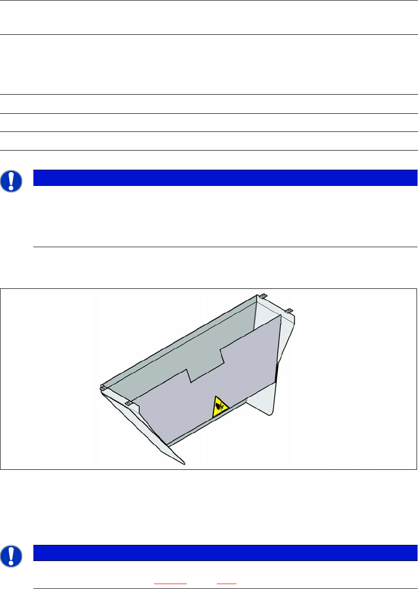
Fig. 3.9 - 10 Used tape chute for the component trolley COT insert
In accordance with the PCB conveyor height, the length of the used tape chute can be set so that
the tape cuttings are directly diverted into the waste tape container of the component trolley.
3
Without mount for the
additional tape reel
With mount for the
additional tape reel
PCB conveyor
height
of the component
trolley
Tape reel diameter Tape reel diameter
without spindle with spindle
900 mm 19" 17" 15"
930 mm 19" 19" 17"
950 mm 19" 19" 19"
PLEASE NOTE
Using spindles
SIPLACE X-Series S component trolleys do not generally need spindles.
Use spindles if the error message "Timeout" appears frequently on the X feeder
module.
PLEASE NOTE
The used tape chute for the X-Series S can only be installed on the COT insert
for the X-Series S (see fig. 5.14 - 3
, page 283).
3 Technical data and assemblies Instruction manual SIPLACE X-Series
3.9 Component trolley From software version 713.0 Edition 11/2019
182
3.9.10 Empty tape duct on the component trolley COT insert
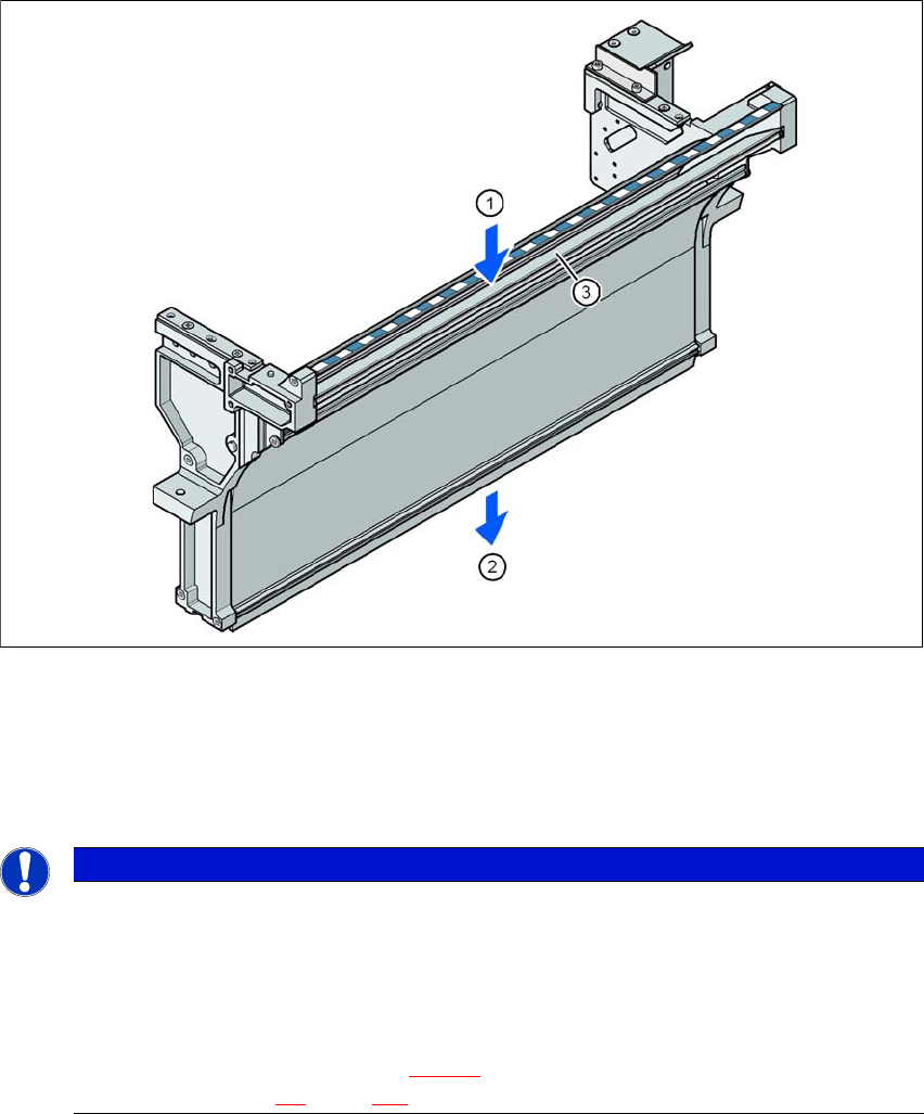
In the standard version, the empty tape duct can guide component tapes with a maximum pocket
height of 8 mm to the pneumatic tape cutter.
3
Fig. 3.9 - 11 Empty tape duct on the SIPLACE X-Series S COT insert
(1) Inlet slot for used tape
(2) Outlet slot for the used tape above the pneumatic tape cutter
(3) Dividing plate for tapes < 8 mm (can be removed for tapes > 8 mm)
3
PLEASE NOTE
Risk of blockages!
When using feeder modules with low pockets next to feeder modules with high pockets,
there is a risk of blockages in the empty tapes.
Do not position feeder modules with shallow pockets immediately beside feeder
modules with deep pockets.
The separating plate (item 3 in fig. 3.9 - 11
) can be removed for tape pockets higher than
12 mm (see section 4.5
, page 225).