00198711-01_UM_X-Serie-S_EN.pdf - 第189页
Instruction manual SIPLACE X-Seri es S 4 Setting up and commissioning From software version 713.0 Edition 11/2019 4.1 Transportation and delivery co nfiguration 189 4 4 Fig. 4.1 - 3 Contact surfaces - forks p a rallel to…
4 Setting up and commissioning Instruction manual SIPLACE X-Series S
4.1 Transportation and delivery configuration From software version 713.0 Edition 11/2019
188
4.1.5.2 Means of transport
Use a fork-lift truck with the following specification to carry the placement machine:
4.1.5.3 Fork-lift attachment points on the placement machine
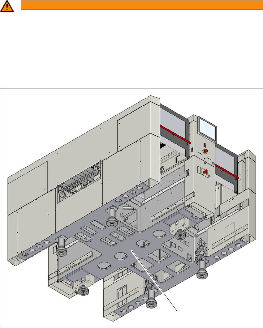
The diagram 4.1 - 3, page 189 shows the fork-lift attachment points on the placement machine for
lifting the placement machine off the pallet or transporting it without the pallet.
4
4
Please note the warnings before you raise the placement machine in order to avoid irrevers-
ible damage to the placement machine:
4
4
Fork length Min. 1800 mm
Lifting power Min. 6,000 kg
Distance between forks with the forks running parallel
to the direction of PCB transport
Approx. 420 mm
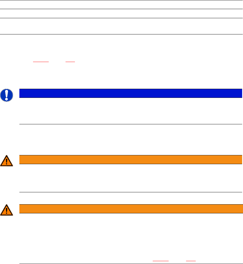
PLEASE NOTE
Avoiding damage to the placement machine
When transporting the placement machine over longer distances, always use a pal-
let and fork lift.
WARNING
Aligning the forks
– The forks must be aligned parallel to the PCB conveyor.
– The forks must be aligned parallel to the placement machine.
WARNING
Risk of damage due to excessive fork spacing!
Increased fork spacing, which means that the placement machine is raised at points out-
side its contact surface, can lead to deformation of the placement machine frame and
cause damage to cables and lines.
The forks may only be opened to a degree which ensures that they are still within the
contact area of the machine underside (see fig. 4.1 - 3
, page 189).
Instruction manual SIPLACE X-Series S 4 Setting up and commissioning
From software version 713.0 Edition 11/2019 4.1 Transportation and delivery configuration
189
4
4
Fig. 4.1 - 3 Contact surfaces - forks parallel to the direction of PCB transport (example of SIPLACE X3 S / X4 S
shown)
(1) Contact surface for fork lift truck forks
4
4
WARNING
Risk of damage due to one-sided loading!
One-sided loading of the machine feet e.g. from tilting the placement machine, can lead
to deformation of the machine feet fixtures.
Make sure that the forks are evenly loaded when you lift the placement machine.
Use a firm support layer between the forks and the placement machine.
Enlist the help of a second person to watch while you lift the placement machine and
make sure that the placement machine does not tip over to one side.
(1)

4 Setting up and commissioning Instruction manual SIPLACE X-Series S
4.1 Transportation and delivery configuration From software version 713.0 Edition 11/2019
190
4.1.5.4 Points that MUST be noted when transporting the machine
4
4
WARNING
Risk of damaging the machine feet!
The thread for the machine feet in the placement machine frame could be damaged by
it being dragged along the floor or from impact.
When you are transporting the machine, make sure that all the feet are clear of the
floor.
WARNING
Risk of damaging the exhaust air duct for the vacuum pump!
Vacuum pumps can be fitted in placement area 1. The exhaust air duct is fitted under the
machine base. This exhaust air duct could be damaged during transportation with the
fork-lift.
Dismantle the exhaust air duct before you transport the placement machine with the
fork-lift.