00198711-01_UM_X-Serie-S_EN.pdf - 第191页
Instruction manual SIPLACE X-Seri es S 4 Setting up and commissioning From software version 713.0 Edition 11/2019 4.2 In frastructure at the in stallation location 191 4.2 Infrastructure at the inst allation location 4 4…
4 Setting up and commissioning Instruction manual SIPLACE X-Series S
4.1 Transportation and delivery configuration From software version 713.0 Edition 11/2019
190
4.1.5.4 Points that MUST be noted when transporting the machine
4
4
WARNING
Risk of damaging the machine feet!
The thread for the machine feet in the placement machine frame could be damaged by
it being dragged along the floor or from impact.
When you are transporting the machine, make sure that all the feet are clear of the
floor.
WARNING
Risk of damaging the exhaust air duct for the vacuum pump!
Vacuum pumps can be fitted in placement area 1. The exhaust air duct is fitted under the
machine base. This exhaust air duct could be damaged during transportation with the
fork-lift.
Dismantle the exhaust air duct before you transport the placement machine with the
fork-lift.

Instruction manual SIPLACE X-Series S 4 Setting up and commissioning
From software version 713.0 Edition 11/2019 4.2 Infrastructure at the installation location
191
4.2 Infrastructure at the installation location
4
4.2.1 Recommendations for foundation quality
The floor on which the placement machine is installed must be firm and level, as dynamic forces
could cause vibrations when the placement machine is operated. The degree of vibration depends
on the construction of the foundation. The following are suitable provided that the floor loading pa-
rameters, etc., are not exceeded:
– Reinforced concrete ceiling constructions, e.g. ceilings in production halls
– Reinforced concrete floor slabs, e.g. concrete floors in production halls without a basement
– Rooms with double floors, provided that a stable foundation is included in the space between
them. The same setup conditions apply to this intermediate foundation, which can be made
from steel girders or concrete.
4
4.2.1.1 Maximum ground levelness
The floor underneath the placement machine may not exceed an incline of 0.63%. This corre-
sponds to an incline of 5 mm over a distance of 800 mm (e.g. the width of a changeover table).
4.2.1.2 Machine weight and floor loading
The machine weight and floor loading values can be found in section 3.3.1, page 110.
PLEASE NOTE
Also observe the document "Network and compressed air configuration for SMD sys-
tems" (German+English, Item No. 00197548-xx), which is supplied with your SIPLACE
placement machine.
4 Setting up and commissioning Instruction manual SIPLACE X-Series S
4.2 Infrastructure at the installation location From software version 713.0 Edition 11/2019
192
4.2.2 Compressed air supply
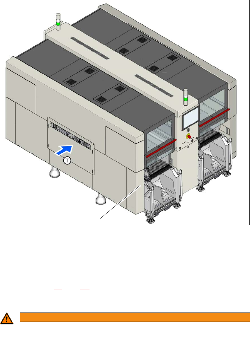
Fig. 4.2 - 1 Position of compressed air supply in the placement machine
(1) Installation position of compressed air supply
4.2.2.1 Checking the compressed air supply
Check whether the compressed air supply complies with the prescribed machine specifications
(see table in section 3.2
, page 107).
Record the compressed air characteristics at the installation location.
4
1
WARNING
Risk of injuries!
Risk of injuries from pressurized compressed air lines.
NEVER detach compressed air lines while they are still pressurized.