00198711-01_UM_X-Serie-S_EN.pdf - 第193页
Instruction manual SIPLACE X-Seri es S 4 Setting up and commissioning From software version 713.0 Edition 11/2019 4.2 In frastructure at the in stallation location 193 4.2.2.2 Compressed air connection on the p lacement …
4 Setting up and commissioning Instruction manual SIPLACE X-Series S
4.2 Infrastructure at the installation location From software version 713.0 Edition 11/2019
192
4.2.2 Compressed air supply
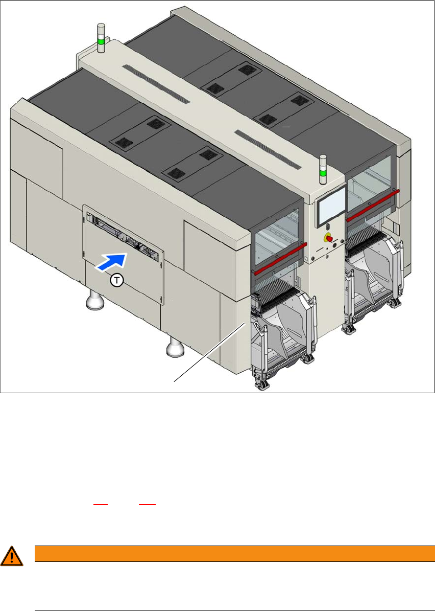
Fig. 4.2 - 1 Position of compressed air supply in the placement machine
(1) Installation position of compressed air supply
4.2.2.1 Checking the compressed air supply
Check whether the compressed air supply complies with the prescribed machine specifications
(see table in section 3.2
, page 107).
Record the compressed air characteristics at the installation location.
4
1
WARNING
Risk of injuries!
Risk of injuries from pressurized compressed air lines.
NEVER detach compressed air lines while they are still pressurized.
Instruction manual SIPLACE X-Series S 4 Setting up and commissioning
From software version 713.0 Edition 11/2019 4.2 Infrastructure at the installation location
193
4.2.2.2 Compressed air connection on the placement machine
4
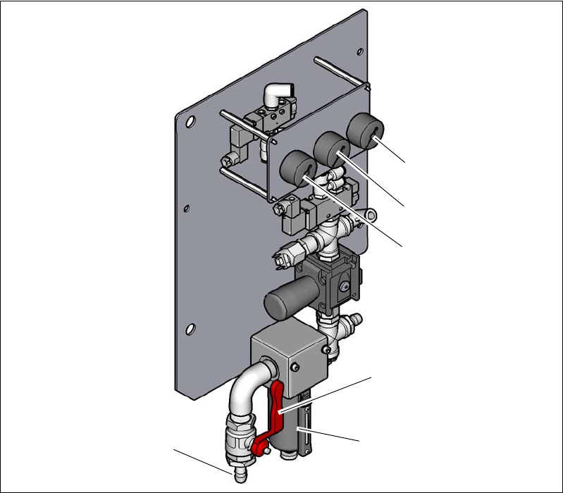
Fig. 4.2 - 2 Compressed air unit on the placement machine
Legend for fig.4.2 - 2
(1) Manometer for the machine component supply pressure
Target pressure: 0.5 ± 0.025 MPa, 5 ± 0.25 bar (display range 0 - 1.0 MPa, 0 - 10 bar)
(2) Manometer for supply pressure of gantries 1 to 4
Target pressure: 0.46 ± 0.01 MPa, 4.6 ± 0.1 bar (display range 0 - 1.0 MPa, 0 - 10 bar)
(3) Manometer for inlet pressure
Target pressure: 0.5 - 1.0 MPa, 5 - 10 bar (display range: 0 - 1.0 MPa, 0 - 10 bar)
(4) Stop valve in the "OPEN" position
(5) Compressed air filter
(6) Compressed air connection
(6)
(1)
(2)
(3)
(5)
(4)
4 Setting up and commissioning Instruction manual SIPLACE X-Series S
4.2 Infrastructure at the installation location From software version 713.0 Edition 11/2019
194
4.2.3 Main power supply
4
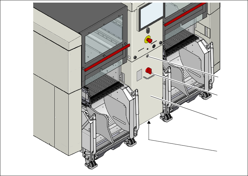
Fig. 4.2 - 3 Position of power supply on the placement machine (example of SIPLACE X2 S / X3 S / X4 S shown)
(1) Lock
(2) Main power switch secured to prevent switching on again
(3) Power supply unit (behind the cover)
(4) Main connection cable from below to the power supply
(1)
(2)
(3)
(4)