00198711-01_UM_X-Serie-S_EN.pdf - 第208页
4 Setting up and commissioning Instruct ion manual SIPLACE X-Series S 4.3 Setting up the placement machine From software version 713.0 Edition 11/2019 208 4 With the fork-lif t, raise the placement machine approximatel…
Instruction manual SIPLACE X-Series S 4 Setting up and commissioning
From software version 713.0 Edition 11/2019 4.3 Setting up the placement machine
207
4.3.6 Presetting board conveyor height
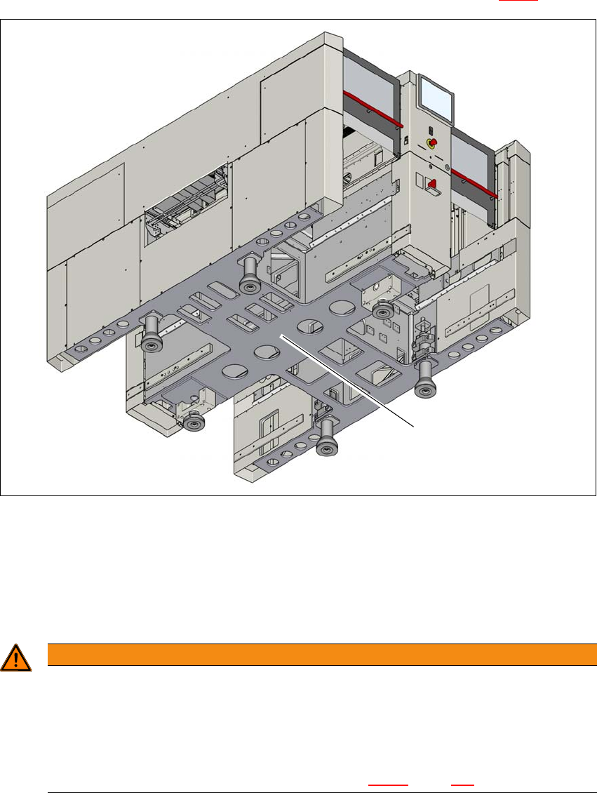
Push the forks of the fork lift under the placement machine, as shown in fig. 4.3 - 2.
4
Fig. 4.3 - 2 Contact surfaces - forks parallel to the direction of PCB transport (example of SIPLACE X2 S / X3 S / X4
S shown)
(1) Contact surfaces for fork lift truck forks
Please note the following points before you raise the placement machine in order to avoid irre-
versible damage to the placement machine:
4
WARNING
Risk of damage due to excessive fork spacing!
The spacing of the machine feet is 776 mm. Increasing this spacing, so that the place-
ment machine is lifted up via the side sections of its machine frame, can lead to defor-
mation of the machine frame.
The forks may only be opened to a degree which ensures that they are still within
the contact area of both machine feet (see fig. 4.3 - 2
, page 207).
(1)
4 Setting up and commissioning Instruction manual SIPLACE X-Series S
4.3 Setting up the placement machine From software version 713.0 Edition 11/2019
208
4
With the fork-lift, raise the placement machine approximately 35 cm. This prevents the risk of
any injuries to your feet if the machine feet are unintentionally lowered.
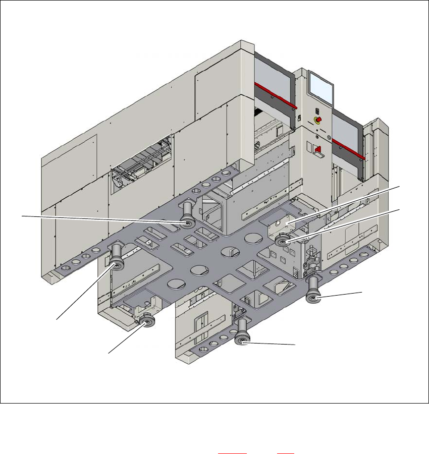
The placement machine stands on 6 feet.
– 4 outer machine feet (item 1 in fig. 4.3 - 4
, page 209 )
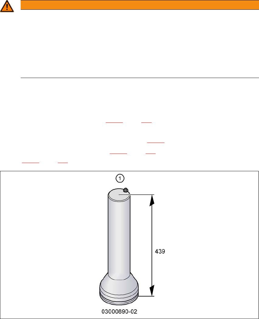
– Outer machine feet for the PCB conveyor heights 900,930 and 950 mm, length
439 mm, Item no. 03000890-02 (item 1 in fig. 4.3 - 3
).
– 2 middle machine feet (item 2 in fig. 4.3 - 4
, page 209) with 2 spacers (item 3 and item 4 in
fig. 4.3 - 4
, page 209) for height adjustment, where necessary.
4
Fig. 4.3 - 3 Outer machine feet - two versions (dimensions in millimeters)
WARNING
Risk of damage due to one-sided loading!
One-sided loading of the machine feet e.g. from tilting the placement machine, can lead
to deformation of the machine feet fixtures.
Make sure that the forks are evenly loaded when you lift the placement machine.
Use a firm support layer between the forks and the placement machine.
Enlist the help of a second person to watch while you lift the placement machine and
make sure that the placement machine does not tip over to one side.
Instruction manual SIPLACE X-Series S 4 Setting up and commissioning
From software version 713.0 Edition 11/2019 4.3 Setting up the placement machine
209
4
Fig. 4.3 - 4 Placement machine feet (example of SIPLACE X2 S / X3 S / X4 S shown)
4
(1) Outer machine foot, 4 x, 2 versions (see fig. 4.3 - 3, page 208 )
(2) Middle machine foot, 2 x
(3) Spacer on the side of the power supply unit
(2)
(2)
(1)
(1)
(1)
(1)
(3)