00198711-01_UM_X-Serie-S_EN.pdf - 第216页
4 Setting up and commissioning Instruct ion manual SIPLACE X-Series S 4.3 Setting up the placement machine From software version 713.0 Edition 11/2019 216 4.3.7.1 Machine foot clearances for the PCB dual conveyo r 4 Fig.…
Instruction manual SIPLACE X-Series S 4 Setting up and commissioning
From software version 713.0 Edition 11/2019 4.3 Setting up the placement machine
215
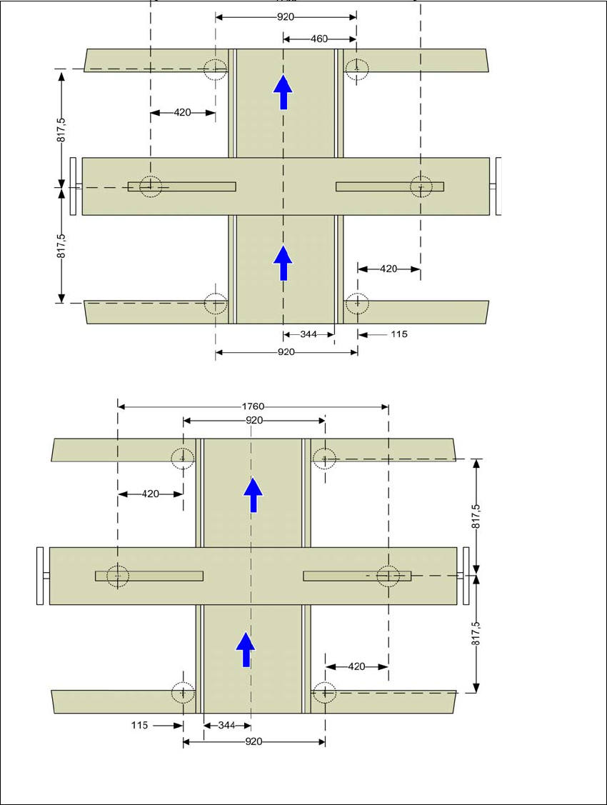
4.3.7 Machine foot clearances and the stationary PCB conveyor edges
Machine foot clearances for the PCB single conveyor
4
Fig. 4.3 - 8 Machine foot clearances for the PCB single conveyor in millimeters
Fixed conveyor side at maximum
right position
a
.
a) The value depends on the position of the fixed side. All dimensions in millimeters.
Fixed conveyor side at maximum
left position
a
.
4 Setting up and commissioning Instruction manual SIPLACE X-Series S
4.3 Setting up the placement machine From software version 713.0 Edition 11/2019
216
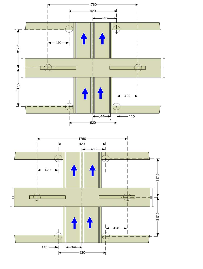
4.3.7.1 Machine foot clearances for the PCB dual conveyor
4
Fig. 4.3 - 9 Machine foot clearances for the PCB dual conveyor in millimeters
Fixed conveyor side at maxi-
mum right position
a
.
a) The value depends on the position of the fixed side. All dimensions in millimeters.
Fixed conveyor side at maxi-
mum left position
a
.
Instruction manual SIPLACE X-Series S 4 Setting up and commissioning
From software version 713.0 Edition 11/2019 4.3 Setting up the placement machine
217
4.3.8 Integrating the placement machine into the line
Observe the general warnings in section 4.3.1, page 202.
Observe the warnings for transportation of the placement machine in section 4.3.2, page 203.
For details of tools and equipment, refer to section 4.3.5, page 206.
4.3.8.1 Aligning and adjusting the placement machines in the line
With the fork-lift, raise the placement machine until the weight is taken off the machine feet.
Determine the PCB conveyor height for the placement machine in the line and use the hexa-
gon socket head screw to adjust the height approximately.
You may need to fit the machine feet to the relevant PCB conveyor height (see 4.3.6 on page
207).
Position the placement machine on the free location on the line using the fork-lift.
Pay attention to the alignment of the PCB conveyors and check the distance to the previous
placement machine.
4
4
WARNING
Risk of damage!
If the machine feet on one side hit the ground hard, the fixings may be damaged.
Slowly lower the placement machine.
A second person should look underneath to ensure that all the machine foot touch
the floor at the same time.