00198711-01_UM_X-Serie-S_EN.pdf - 第219页
Instruction manual SIPLACE X-Seri es S 4 Setting up and commissioning From software version 713.0 Edition 11/2019 4.3 Setting up the placement machine 219 4 Fig. 4.3 - 1 1 Presetting the height of the outer machine feet …
4 Setting up and commissioning Instruction manual SIPLACE X-Series S
4.3 Setting up the placement machine From software version 713.0 Edition 11/2019
218
Align the placement machine in the X and Y direction with the help of the machine spirit level.
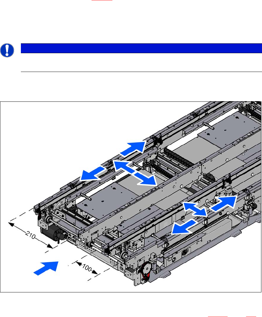
Place the machine spirit level in the X and then the Y direction on the sides of the conveyor
in placement area 1 (see fig. 4.3 - 10
). The board conveyor width has been preset:
Single conveyor 210 mm
Dual conveyor, lane 1 100 mm
Dual conveyor, lane 2 210 mm 4
4
Measure the distance between the upper edge of the PCB conveyor belt and the underside.
This distance should be 900 mm, 930 mm or 950 mm.
4
Fig. 4.3 - 10 Adjusting the placement machine in the X and Y directions
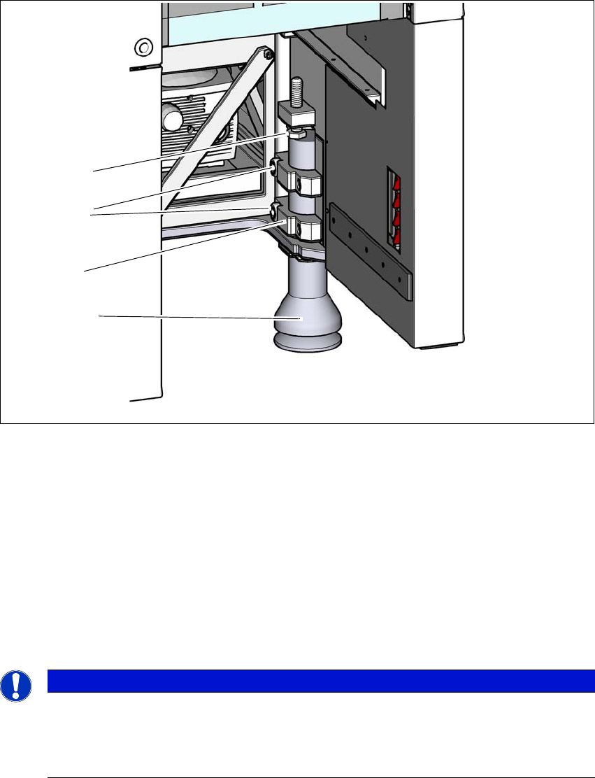
Use the fork wrench to adjust the setting screw M24x2x120 (item 1 in fig. 4.3 - 11, page 219),
so that the fluid in the machine spirit level does not deviate from its zero point at the required
conveyor height.
PLEASE NOTE
When using a dual conveyor, always place the spirit level on the outer sides of the
placement machine for measuring the X direction.
Instruction manual SIPLACE X-Series S 4 Setting up and commissioning
From software version 713.0 Edition 11/2019 4.3 Setting up the placement machine
219
4
Fig. 4.3 - 11 Presetting the height of the outer machine feet
(1) Setting screw M24x120 for height adjustment (M24x100 at 900 mm machine height)
(2) Outer machine foot
(3) Clamping piece
(4) Hexagon socket-head screw M24x90
Check the required board conveyor height.
Once the placement machine has been aligned, use the torque wrench to tighten the hexagon
socket-head screws M24x90 (item 4) to clamp the clamping pieces at all outer machine feet
(item 3).
4
Use the hook wrench to unscrew the middle machine feet roughly 135 - 145, until these are
positioned firmly on the ground.
Make sure that the middle machine feet are not screwed out too far, thereby unbalancing the
placement machine.
PLEASE NOTE
Vibration at low tightening torques!
The tightening torque is 130 Nm. A lower torque could cause the placement machine to
vibrate.
Use a sufficiently high tightening torque.
(4)
(2)
(1)
(3)
4 Setting up and commissioning Instruction manual SIPLACE X-Series S
4.3 Setting up the placement machine From software version 713.0 Edition 11/2019
220
4
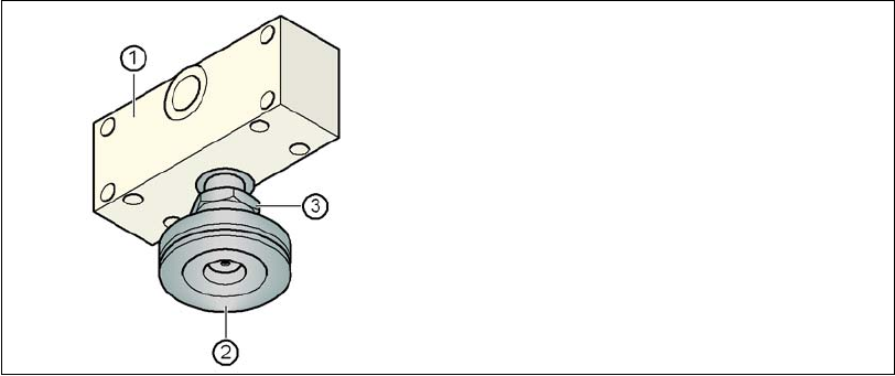
Fig. 4.3 - 12 Aligning and locking the middle machine feet
Use the spirit level to ensure that the placement machine is precisely aligned.
Use the fork wrench SW65 to tighten the lock nut M24 (item 3).
(1) Spacer
(2) Middle machine foot
(3) Lock nut M24