00198711-01_UM_X-Serie-S_EN.pdf - 第235页
Instruction manual SIPLACE X-Series S 5 Tasks at the placement machine From software version 713.0 Edition 11/2019 5.2 Controls and displays 235 5.2 Controls and displays 5.2.1 Overview 5 Fig. 5.2 - 1 Controls and displa…
5 Tasks at the placement machine Instruction manual SIPLACE X-Series S
5.1 Staff profiles From software version 713.0 Edition 11/2019
234
5.1.3 Operator level "Service (customer)"
5.1.3.1 Tasks
The service personnel's duties include:
– Major preventive maintenance jobs
– Mounting replacement parts
– Editing machine data
– Calibrating the placement machine
Instruction manual SIPLACE X-Series S 5 Tasks at the placement machine
From software version 713.0 Edition 11/2019 5.2 Controls and displays
235
5.2 Controls and displays
5.2.1 Overview
5
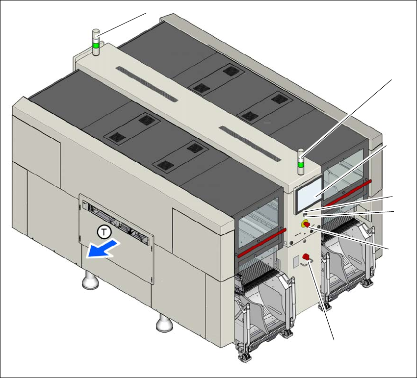
Fig. 5.2 - 1 Controls and displays (example of SIPLACE X2 S / X3 S / X4 S shown)
(1) Main switch (5) Multitouch monitor
(2) Stop button (black) (6) Indicator lamps with horn
(3) EMERGENCY STOP button (T) Direction of PCB transport
(4) Start button (white)
(1)
(2)
(3)
(4)
(5)
(6)
(7)

5 Tasks at the placement machine Instruction manual SIPLACE X-Series S
5.2 Controls and displays From software version 713.0 Edition 11/2019
236
5.2.2 Description
All the controls can be reached by a 1.40 m tall person.
Main switch 5
The main power switch is used to switch the power supply to the placement machine on and off.
5
Stop button (black) 5
This black button is used to stop the placement process at the placement machine.
Start button (white) 5
This white button starts the placement machine after it has been switched on or after faults have
been eliminated.
EMERGENCY STOP button 5
The EMERGENCY STOP button latches in the ON position when pressed. The power supply to
the gantry axes, the component trolleys, conveyors and used tape cutters is interrupted and the
voltage supplied to the star axes of the placement heads is reduced. Turn the button to release it.
Multitouch monitor 5
On each side of the placement machine, there is a flat screen with a highly sensitive "multi-touch"
surface (screen with multi-finger gesture recognition). Use the station software to show a key-
board for screen entries.
Indicator lamp with horn - two color (standard) 5
The sequence of colors of the indicator lamps is white - green. These lamps are used to signal
operating statuses and malfunctions of the placement machine. See also Section 5.7 on page
253.
Indicator lamp with horn - three color (optional) 5
The sequence of colors of the indicator lamps is red - yellow - green. These lamps are used to
signal operating statuses and malfunctions of the placement machine. See also Section 5.7 on
page 253.
DANGER
Lethal voltages!
Some parts inside the placement machine carry potentially lethal voltages - even when
switched off at the main power switch.