00198711-01_UM_X-Serie-S_EN.pdf - 第25页
Instruction manual SIPLACE X-Series S 1 Introduction From software version 713.0 Edition 11/201 9 1.2 Placement machine description 25 1.2.4 SIPLACE X2 S 1 Fig. 1.2 - 4 SIPLACE X2 S placement machine The SIPLACE X2 S pla…

1 Introduction Instruction manual SIPLACE X-Series S
1.2 Placement machine description From software version 713.0 Edition 11/2019
24
There are four locations available for supplying components. These can be fitted with component
trolleys and configured with up to 40 tracks.
The SIPLACE X3 S placement machine has three gantries. The two gantries in placement area 1
point to location 4. The gantry in placement area 2 points to location 2.
These can be quickly and accurately positioned by linear motors, moving independently of one
another in the X and Y directions.
1.2.3.1 Overview of placement head configuration
1
CPP_H = SIPLACE Multistar CPP in high assembly position
CPP_L = SIPLACE Multistar CPP in low assembly position
Placement area 1 Placement area 2
C&P20 P / C&P 20 P C&P20 P
C&P20 P / C&P 20 P CPP_L
C&P20 P / C&P 20 P CPP_H
C&P20 P2 / C&P 20 P2 C&P20 P2
C&P20 P2 / C&P 20 P2 CPP_L
C&P20 P2 / C&P 20 P2 CPP_H
CPP_L/CPP_L CPP_L
CPP_H / CPP_H CPP_H
CPP_L/CPP_L CPP_H
C&P20 / C&P 20 TH
CPP_L/CPP_L TH
CPP_H / CPP_H TH
TH / TH TH
Instruction manual SIPLACE X-Series S 1 Introduction
From software version 713.0 Edition 11/2019 1.2 Placement machine description
25
1.2.4 SIPLACE X2 S
1
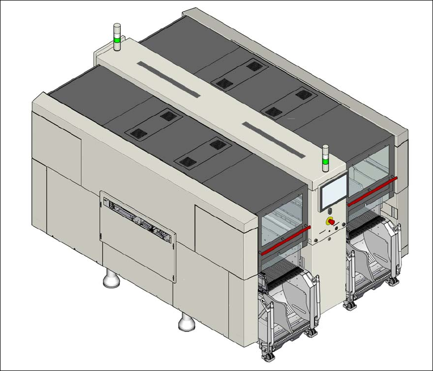
Fig. 1.2 - 4 SIPLACE X2 S placement machine
The SIPLACE X2 S placement machine is distinguished by
– High precision,
– Intelligent placement optimization,
– Intelligent configuration strategies,
– Placement performance up to the high end process range
Three placement methods are possible for processing the components:
– Collect&Place,
– Pick&Place and
– A combination of Collect&Place and Pick&Place (mixed mode).
The SIPLACE X2 S placement machine has two placement areas, one single conveyor or one
dual conveyor. Two boards can be placed at the same time on dual conveyors.

1 Introduction Instruction manual SIPLACE X-Series S
1.2 Placement machine description From software version 713.0 Edition 11/2019
26
There are four locations available for supplying components. These can be fitted with component
trolleys and configured with up to 40 tracks.
The SIPLACE X2 S placement machine has two gantries. The gantry in placement area 1 points
to location 4. The gantry in placement area 2 points to location 2.
These can be quickly and accurately positioned by linear motors, moving independently of one
another in the X and Y directions.
1.2.4.1 Overview of placement head configuration
1
CPP_H = SIPLACE Multistar CPP in high assembly position
CPP_L = SIPLACE Multistar CPP in low assembly position
Placement area 1 Placement area 2
C&P20 P C&P20 P
C&P20 P CPP_L
C&P20 P CPP_H
C&P20 P2 C&P20 P2
C&P20 P2 CPP_L
C&P20 P2 CPP_H
CPP_L CPP_L
CPP_H CPP_H
CPP_L CPP_H
C&P20 P TH
C&P20 P2 TH
CPP_L TH
CPP_H TH
TH TH