00198711-01_UM_X-Serie-S_EN.pdf - 第268页
5 Tasks at the placement machine Ins truction manual SIPLACE X-Series S 5.10 Setting up the feeder modules From software version 713.0 Edition 11/2019 268 5.10.3.2 Inserting the X feeder module into the changeover t able…
Instruction manual SIPLACE X-Series S 5 Tasks at the placement machine
From software version 713.0 Edition 11/2019 5.10 Setting up the feeder modules
267
If the removal handle (item 1) is still protruding, then latch it in place.
5
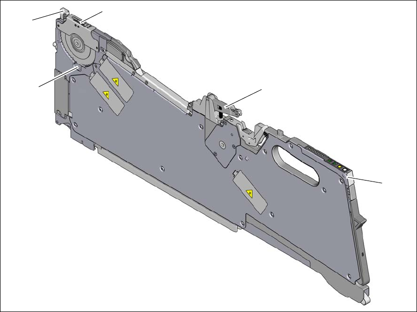
Fig. 5.10 - 2 Check the X feeder module before using it
(1) Removal handle
(2) Cover foil rocker
(3) Pickup window
(4) Lever for raising and latching the pick-up window
(5) Component disposal compartment
(1)
(2)
(3)
(4)
(5)
5 Tasks at the placement machine Instruction manual SIPLACE X-Series S
5.10 Setting up the feeder modules From software version 713.0 Edition 11/2019
268
5.10.3.2 Inserting the X feeder module into the changeover table
5
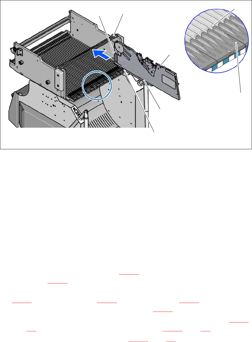
Fig. 5.10 - 3 Inserting the X feeder module into the changeover table
(1) Front slider guide for the X feeder module
(2) Back slider guide for the X feeder module
(3) "Back" centering pin on the X feeder module
(4) "Front" centering pin on the X feeder module
(5) Recesses in the centering bar for holding the "back" centering pin
(6) Centering holes on the changeover table for holding the "front" centering pin
(7) Locking latches
(8) Guide profile for the changeover table (Ω profile)
(9) Insertion aid for the feeder module
5
Place the front slider guide (item 1 in fig. 5.10 - 3) of the feeder module on the insertion aid
(item 9 in fig. 5.10 - 3
) of the changeover table.
Hold the feeder module vertically and push it forward, along the guide profile (item 8 in fig.
5.10 - 3
). The front (item 1 in fig. 5.10 - 3) and rear (item 2 in fig. 5.10 - 3) slider guides of the
feeder module slide on the guide profile (item 8 in fig. 5.10 - 3
).
Carefully push the feeder module further until the "front" centering pin (item 4 in fig. 5.10 - 3,
page 268
) is pushed into the centering hole (item 6 in fig. 5.10 - 3, page 268).
Check the "back" centering pin (item 3 in fig. 5.10 - 3, page 268) of the feeder module as you
do so. This must slide easily into the recess (item 5) in the centering bar, otherwise the feeder
(8)
(9)
(5)
(3)
(2)
(1)
(4)

Instruction manual SIPLACE X-Series S 5 Tasks at the placement machine
From software version 713.0 Edition 11/2019 5.10 Setting up the feeder modules
269
module is not seated vertically on the changeover table or it was not placed on the guide pro-
file (item 8 in fig. 5.10 - 3
, page 268) correctly.
When the feeder module is at the stop position, the locking latch (item 7 in fig. 5.10 - 3, page
268
) engages onto the locking roller of the feeder module. If you
have forgotten to engage the removal handle (item 1 in fig. 5.10 - 2
, page 267) the status dis-
play
on the feeder module's operator panel will light up red after a few seconds.
Engage the removal handle (item 1 in fig. 5.10 - 2, page 267). The feeder module's status
display now lights up green and the feeder module is on standby.