00198711-01_UM_X-Serie-S_EN.pdf - 第272页
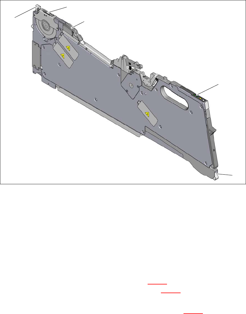
5 Tasks at the placement machine Ins truction manual SIPLACE X-Series S 5.10 Setting up the feeder modules From software version 713.0 Edition 11/2019 272 5 Fig. 5.10 - 5 Pickup window on the tape feeder module (1) T ape…
Instruction manual SIPLACE X-Series S 5 Tasks at the placement machine
From software version 713.0 Edition 11/2019 5.10 Setting up the feeder modules
271
5.10.4.3 Inserting the tape into the X feeder module
5
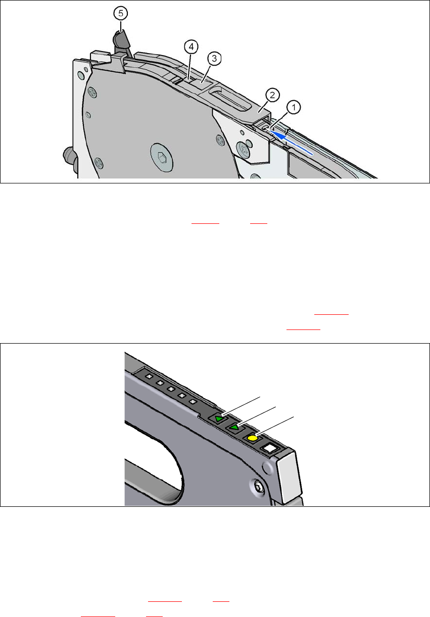
Fig. 5.10 - 4 Inserting the component tape
(1) Entry to the tape guide channel
(2) Operator panel
(3) Tape guide channel outlet
(4) Pickup window
(5) Lever for raising the pickup window
5
Hold the component tape so that the transport holes are on the left-hand side viewed in the
direction of travel.
Push the component tape into the entry (item 1 in fig. 5.10 - 4) to the tape guide channel and
further until it emerges from the exit opening (item 3 in fig. 5.10 - 4
).
Pull the component tape up and out, and fold the cover foil back against the top of the tape.
Guide the start of the tape beneath the pickup window (item 2 in fig. 5.10 - 5) and further until
the component tape is touching the sprocket wheel.
(1)
(2)
(3)
(4)
(5)
5 Tasks at the placement machine Instruction manual SIPLACE X-Series S
5.10 Setting up the feeder modules From software version 713.0 Edition 11/2019
272
5
Fig. 5.10 - 5 Pickup window on the tape feeder module
(1) Tape support, removable (see section 5.10.5, page 273)
(2) Pickup window
(3) Removal edge for the cover foil
(4) Component pickup area
(5) Lever for raising and latching the pick-up window
On the operator panel, press the FORWARD button (item 1 in fig. 5.10 - 6) until the bend of
the cover foil is in the component pickup area (item 4 in fig. 5.10 - 5
).
5
Fig. 5.10 - 6 Operating panel with LED display
(1) FORWARD button for moving the component tape forward
(2) BACK button for moving the component tape back
(3) FOIL button for tensioning the cover foil
Push the lever (item 5 in fig. 5.10 - 5, page 272) forward in order to raise the pickup window
(item 2 in fig. 5.10 - 5
, page 272) into the first latching position.
(1)
(2)
(3)
Instruction manual SIPLACE X-Series S 5 Tasks at the placement machine
From software version 713.0 Edition 11/2019 5.10 Setting up the feeder modules
273
Pull the cover foil at the side of the pick-up window forward and out underneath the pick-up
window.
Fold the cover foil back until it lies against the pull-off edge (item 3 in fig. 5.10 - 5, page 272).
5
Push the lever (item 5 in fig. 5.10 - 5, page 272) back to lower the pickup window.
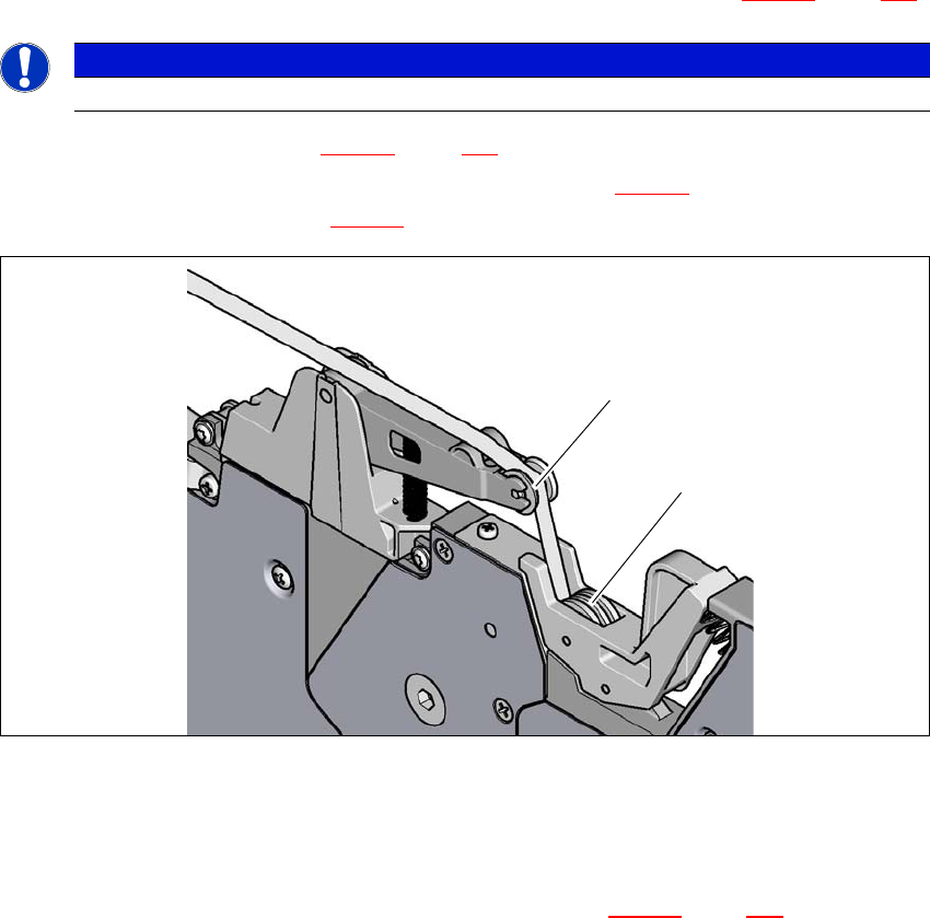
Guide the cover foil over the cover foil rocker (item 2 in fig. 5.10 - 7) until it reaches the foil
packing wheels (item 1 in fig. 5.10 - 7
).
5
Fig. 5.10 - 7 Guiding the cover foil to the foil packing wheels
(1) Cover foil packing wheels
(2) Cover foil
5
On the operator panel, press the FOIL button (item 3 in fig. 5.10 - 6, page 272) until the cover
foil is tensioned. The cover foil rocker points down and stops the drive motor.
Cut the component tape flush with the front end of the feeder module.
5.10.5 Configuring components on the SIPLACE SmartFeeder
The operation and setting up is described in the SIPLACE SmartFeeder X /Xi job guides.
PLEASE NOTE
Do not lower the pick-up window until the cover foil is lying against the pull-off edge.
(1)
(2)