00198711-01_UM_X-Serie-S_EN.pdf - 第279页
Instruction manual SIPLACE X-Series S 5 Tasks at the placement machine From software version 713.0 Edition 11/2019 5.13 Avoiding track errors 279 5.13.3 Component coordinate system and pickup angle 5 Fig. 5.13 - 1 Positi…
5 Tasks at the placement machine Instruction manual SIPLACE X-Series S
5.13 Avoiding track errors From software version 713.0 Edition 11/2019
278
5.13 Avoiding track errors
5.13.1 General
Make sure that the areas around the feeder modules are clean and that there are no loose
components in the feeder area or under the feeder modules.
Refill promptly with components.
With tape feeder modules, make sure that you always splice on a new tape early enough so
that the feeder modules do not run out of components.
However, do not splice the tapes too early because if you wind the tape onto the new reel
after splicing the end of the old tape, the reel with the new tape may be overfilled. The tape
could then slip off the reel and become tangled. Under certain circumstances, this could
cause pick-up errors and prolonged down times.
5
Splice the tapes early. This generally means that you are to prepare the splicing material
when there is still approximately 1.5 m of tape on the reel.
Handle the feeder modules carefully when you insert them into or remove them from the
changeover table as these are high-precision devices.
For X feeder modules, lower the pickup window since it can easily be damaged when raised.
5
Check that the pick-up position is set correctly for the components on the feeder modules.
5.13.2 Avoiding track errors with the tape container
Insert the separating plates correctly (see fig. 5.9 - 3, page 263).
PLEASE NOTE
The online help contains information on refilling components with and without barcodes.
PLEASE NOTE
A raised pick-up window leads to noticeably impaired pick-up quality.
Instruction manual SIPLACE X-Series S 5 Tasks at the placement machine
From software version 713.0 Edition 11/2019 5.13 Avoiding track errors
279
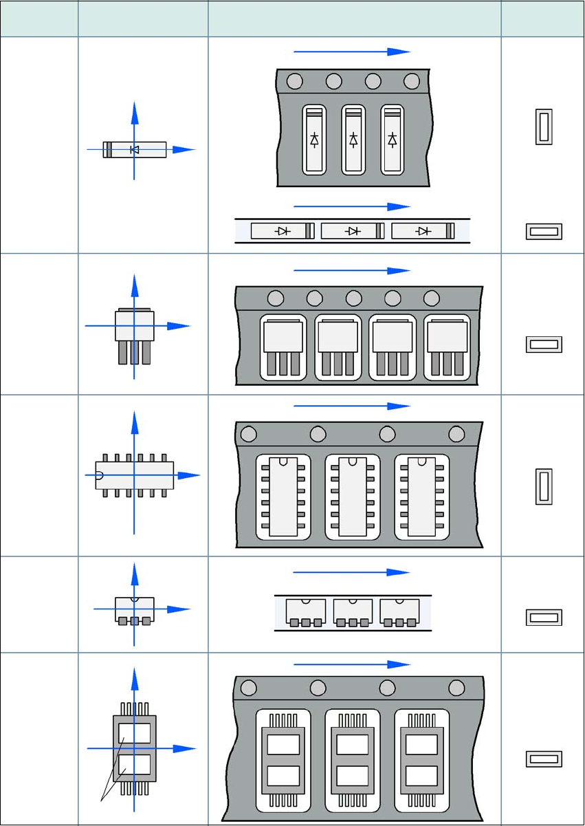
5.13.3 Component coordinate system and pickup angle
5
Fig. 5.13 - 1 Position of the component and its pick-up angle
Special
component
Stick
magazine:
Chip-
components
with polarity
0402
2220
The anode must be
aligned with the +X
coordinate.
Package form 0° coordinate system
Position in the feeder module
Pickup angle/
nozzle angle
Tape:
SOT 23
Stick
magazine:
Tape:
Tape:
SO-IC
DIL-IC
SOT 194
Tape:
Holes
Y
X
Y
X
Y
X
Y
X
Y
X
90°
90°
0°
90°
-90°
0°
5 Tasks at the placement machine Instruction manual SIPLACE X-Series S
5.14 Docking the component trolley in or out From software version 713.0 Edition 11/2019
280
5.14 Docking the component trolley in or out
5.14.1 Safety instructions for docking component trolleys in and out
Also follow the safety instructions given in section 2.5.10, page 73.
5
In addition, the component trolley can only be docked in if the protective
covers are closed.
There is a button at each location (1,2,3 and 4) for docking and undocking the component trolley.
The safety concept for the component trolley changeover specifies that the operator should push
this button at the relevant placement machine location, to dock or undock the component trolley.
WARNING
DANGER OF CRUSHING!
Risk of crushing when docking and undocking the component trolley.
Always dock/undock the component trolley alone.
When docking and undocking, make sure that there are no body limbs in the travel
area of the component trolley.