00198711-01_UM_X-Serie-S_EN.pdf - 第308页
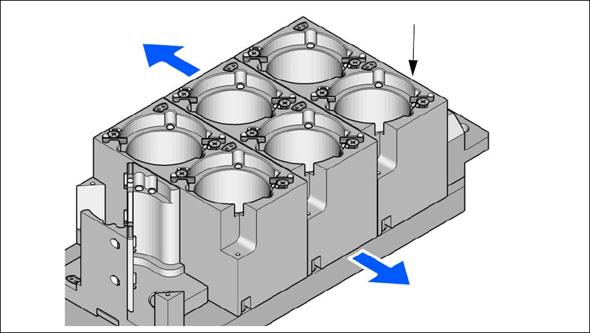
6 Station extensions Instruction manual SIPLACE X-Series S 6.1 Nozzle changer From software version 713.0 Edition 11/2019 308 6.1.4.6 Component reject bin for the SIPLACE T winSt ar A component reject bin can be in stall…
Instruction manual SIPLACE X-Series S 6 Station extensions
From software version 713.0 Edition 11/2019 6.1 Nozzle changer
307
6.1.4.4 Assembly
The nozzle changer is fixed to the COT insert.
6
Fig. 6.1 - 16 Assembly position
(1) Marking hole
(2) Operator side
(3) Arrow pointing toward the PCB conveyor
6
Align the nozzle changer so that the marking hole (item 1) is on the left, as viewed by the op-
erator.
6.1.4.5 Special nozzles
The SIPLACE placement machines process components in accordance with the standard SMT
spectrum.
ASM is continually developing its range of special nozzles.
Special nozzles are available for all placement heads in order to process placement jobs with max-
imum speed, precision and flexibility. The use of automatic nozzle changers also reduces the
setup times that occur at a product change.
For the production of special magazines and grippers, please contact ASM.
(1)
(2)
(3)
6 Station extensions Instruction manual SIPLACE X-Series S
6.1 Nozzle changer From software version 713.0 Edition 11/2019
308
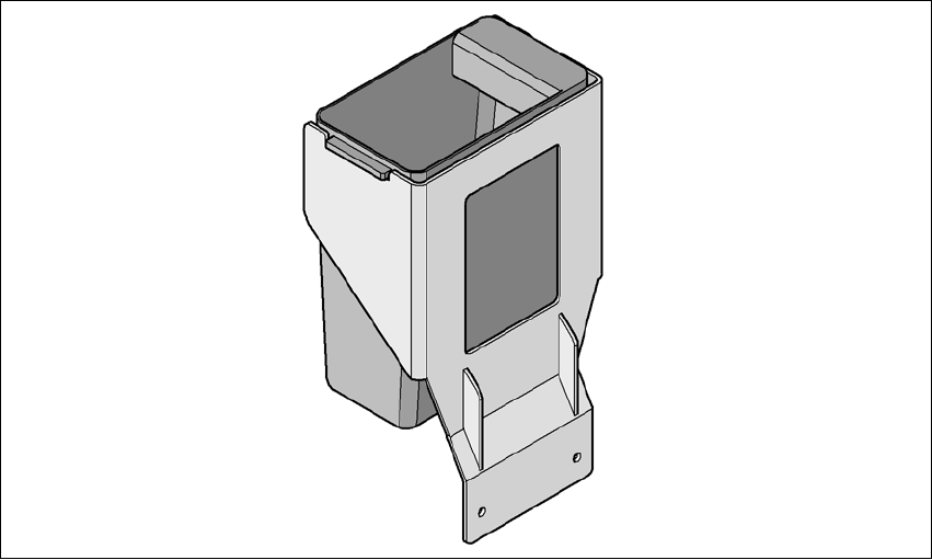
6.1.4.6 Component reject bin for the SIPLACE TwinStar
A component reject bin can be installed for the SIPLACE TwinStar. This is positioned next to the
stationary camera.
6
Fig. 6.1 - 17 Component reject bin for the SIPLACE TwinStar

Instruction manual SIPLACE X-Series S 6 Station extensions
From software version 713.0 Edition 11/2019 6.2 PCB barcode scanner
309
6.2 PCB barcode scanner
6.2.1 Description
The PCB barcode reader is used to automatically record and decode barcodes on PCBs. The
PCB barcode scanners are installed on a special frame on the input side of the placement ma-
chine on the PCB
conveyor. Depending
on the position of the barcode strips, the barcode scanner can be attached in a few simple
steps so that the strips can be read parallel to or across the PCB transport direction.
When using dual conveyors, four board barcode readers can be retrofitted. These can scan both
the top or bottom of the boards on both conveyor lanes.
There are two variants of the barcode scanner:
– 2D board code reader
This code reader processes barcodes and matrix codes. Matrix code is primarily used when
there is
not enough space for barcode labels. 6
6.2.2 Technical data - 2D code reader
6
Dimensions (L x W x H) 55 mm x 42 mm x 22 mm
Weight 125 grams
Code types 2D Data Matrix ECC 0, 50, 80, 100, 140 and 200
Data Matrix ECC200
QR Code, MicroQR Code
Barcode length
Single conveyor
Dual conveyor, asynchronous
Dual conveyor, synchronous
Max. 40 characters
Max. 40 characters
Max. 40 characters
Data interface RS232, USB 2.0
Electrical connection 15-pin D-Sub HD plug
Operating voltage 5 V- to 24 V-