00198711-01_UM_X-Serie-S_EN.pdf - 第333页
Instruction manual SIPLACE X-Series S 6 Station extensions From software version 713.0 Edition 11/2019 6.9 Stationary cameras 333 6.9 St ationary cameras 6.9.1 Component camera, st ationary P&P , type 25 GigE (FC cam…

6 Station extensions Instruction manual SIPLACE X-Series S
6.8 3D coplanarity laser module From software version 713.0 Edition 11/2019
332
6.8.2 Technical data
6
Components QFP, SO, BGA, Gullwing, connector
Accuracy
*a
± 15 μm (3σ), ± 20 μm (4σ)
Maximum component size 50 x 50 mm²
Maximum component height 17 mm
BGA component shape
Min. ball diameter
Min. ball pitch
Min. number of balls
400 μm
800 μm
6
Gullwing component shape
Min. lead width
*b
Min. lead pitch
Min. number of leads
300 μm
500 μm
5
Maximum connector size 120 x 20 mm²
Connector (Gullwing)
Min. lead width
b
Min. lead pitch
Min. number of leads
300 μm
500 μm
5
Placement head type TwinHead, SIPLACE Multistar CPP
Laser protection class
3D coplanarity sensor
Placement machine
3B
2
*)a Per ball/lead
*)b Contact your local product manager for details of smaller lead widths
Instruction manual SIPLACE X-Series S 6 Station extensions
From software version 713.0 Edition 11/2019 6.9 Stationary cameras
333
6.9 Stationary cameras
6.9.1 Component camera, stationary P&P, type 25 GigE (FC camera)
Item no. 03105205-xx Stationary component camera digital, type 25 GigE
6
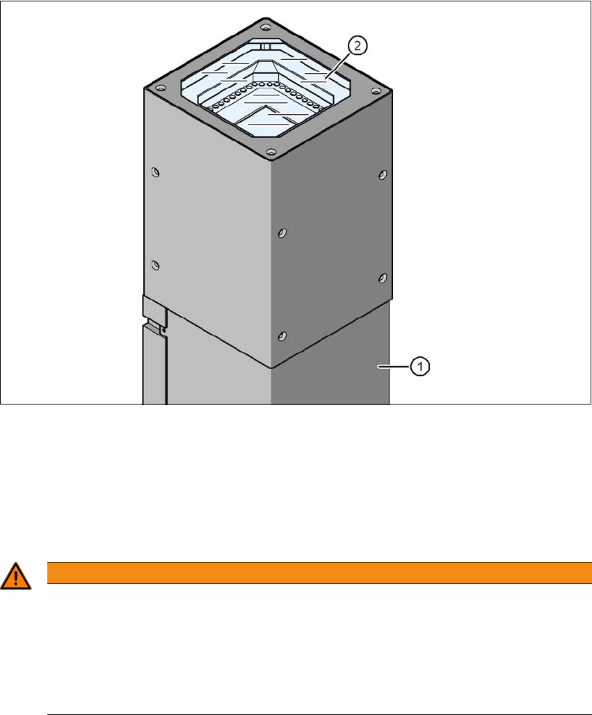
Fig. 6.9 - 1 Component camera, stationary P&P, type 25 GigE (FC camera)
(1) Camera housing with integral camera and camera amplifier
(2) Glass plate - illumination and lens levels below
6.9.1.1 Safety instructions
6
WARNING
Risk of collisions!
When changing the placement head from a TwinStar/VHF to a SpeedStar, the SpeedStar
collides with the camera housing.
Dismantle the stationary component camera for the TwinStar.
When changing the placement head from a TwinStar to a SIPLACE MultiStar CPP,
the stationary component camera is fitted in the bottom position.
6 Station extensions Instruction manual SIPLACE X-Series S
6.9 Stationary cameras From software version 713.0 Edition 11/2019
334
6.9.1.2 Technical data
6
Component dimensions 0.2 mm x 0.2 mm up to 16 mm x 16 mm for single component
measurement
Component range 0402 to SO, PLCC, QFP, sockets, plugs, BGA, special components,
bare dies, flip-chips, shields
Min. lead pitch 0.25 mm
Min. lead width 0.1 mm
Min. ball pitch 0.14 mm
Min. ball diameter 0.08 mm
Field of vision 19.4 mm x 19.4 mm
Illumination type Front-illumination (6 levels, programmable as required)