00198711-01_UM_X-Serie-S_EN.pdf - 第84页
2 Operational safety Instruction manual SIPLACE X-Series S 2.6 Safety features From software version 713.0 Edition 11/2019 84 2.6.4 Safety cutoff (CSB) 2 Fig. 2.6 - 8 Position of the sa fety cutoff (CSB) 2 (1) Safety cut…

Instruction manual SIPLACE X-Series S 2 Operational safety
From software version 713.0 Edition 11/2019 2.6 Safety features
83
Stop button, black (item 2 in fig. 2.6 - 5, page 79 in fig. 2.6 - 6, page 80) 2
These buttons are used to stop the placement machine.
Component counter 2
The number of placed components (component counter) can be read on the station software. For
more information, refer to the Online Help.
EMERGENCY STOP button with forced locking (item 3 in fig. 2.6 - 5, page 79 and in fig. 2.6 - 6,
page
80) 2
The EMERGENCY STOP button is red and latches in the ON position when pressed. When you
press the EMERGENCY STOP button, the switching contact of the EMERGENCY STOP circuit
opens and the safety cutoff (CBS) trips. The intermediate circuit voltage (300 V-) for the gantry
axes and the intermediate circuit voltage (160 V-) for the star axes plus the drive voltage for the
PCB conveyor are switched off. The servo amplifiers for the DP and Z axes are still supplied with
42 V- and therefore held in position. The signaling contact of the EMERGENCY STOP button
opens and the message "EMERGENCY STOP pressed" appears on the screen. The following
modules are deactivated:
– PCB conveyor
– PCB clamping
– Width adjustment
– PCB stopper
– Compressed air supply for empty tape cutter
2
Protective cover switch 1 to 4 (items 1 to 4 in fig. 2.6 - 7, page 81) 2
These switches check whether the protective covers are closed. When they are closed, the
EMERGENCY STOP contact, the signaling contact and also the EMERGENCY STOP circuit are
closed. If one of the covers is opened, the EMERGENCY STOP contact and the signaling contact
will open. Individual components are disabled or remain enabled (see fig. 2.6 - 9
, page 86 ).
Protective cover switch for service flap (optional) 2
This switch checks whether the service flap is closed. When they are closed, the EMERGENCY
STOP contact and the signaling contact are closed. If the service flap is opened, the EMER-
GENCY STOP contact and the signaling contact will open. Individual components are disabled or
remain enabled (see fig. 2.6 - 9
, page 86 ).
PLEASE NOTE
Placement will be interrupted and can then either be continued or canceled once the
placement machine is working correctly again.
2 Operational safety Instruction manual SIPLACE X-Series S
2.6 Safety features From software version 713.0 Edition 11/2019
84
2.6.4 Safety cutoff (CSB)
2
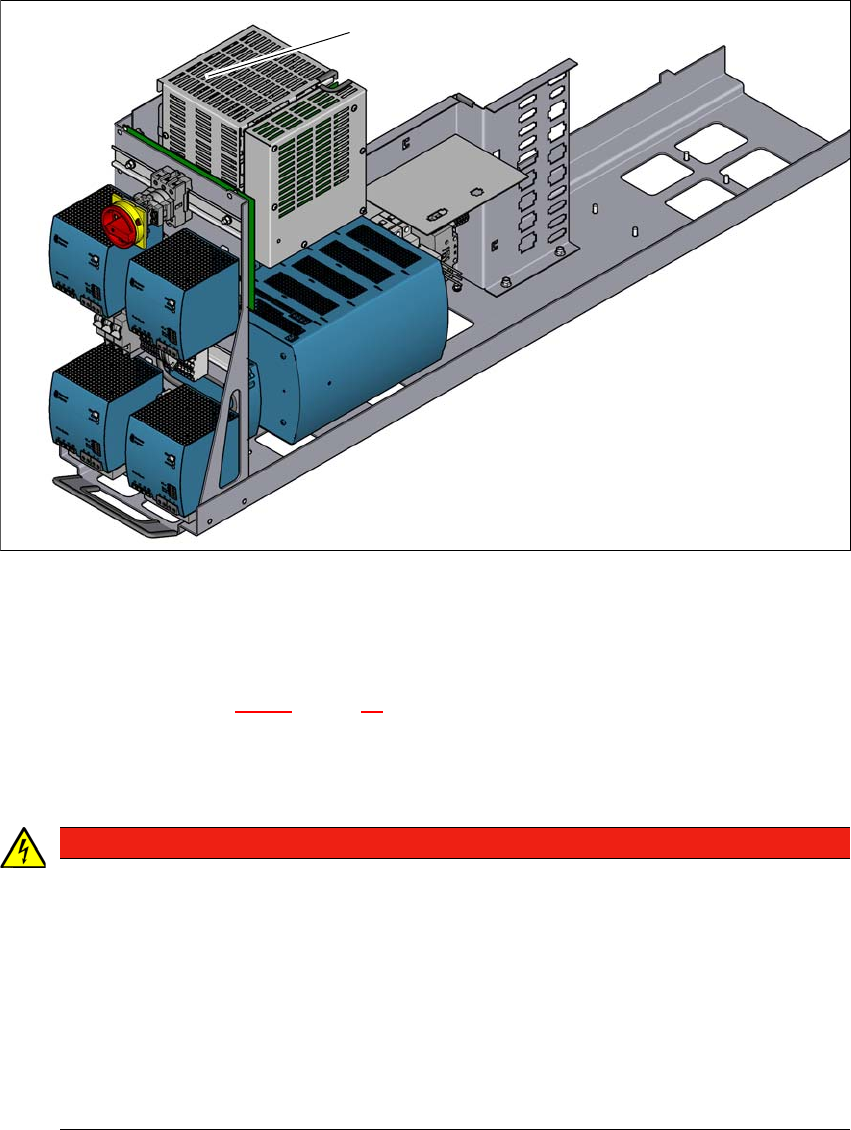
Fig. 2.6 - 8 Position of the safety cutoff (CSB)
2
(1) Safety cutoff (CSB)
Safety cutoff (CSB) (item 1 in fig. 2.6 - 8, page 84) 2
The safety cutoff (CSB) is located in the power supply unit. It is used to monitor the protective fea-
tures and checks for hazardous voltages or movements.
2
(1)
DANGER
Lethal voltages under the safety cutoff (CSB) cover!
Under the cover there are components which could still carry lethal voltages, even when
the placement machine is switched off and the mains plug has been disconnected. After
disconnecting the mains plug, wait approx. 5 minutes until the capacitors have dis-
charged.
Never open the covers.
Only ASM Assembly Systems GmbH&Co.KG service engineers or the machine
owner's service engineers, who have been trained by ASM, may perform work on the
power supply and the safety cutoff (CBS).
Instruction manual SIPLACE X-Series S 2 Operational safety
From software version 713.0 Edition 11/2019 2.6 Safety features
85
There are three conditions that must be fulfilled in order to activate the safety cutoff (CBS):
– All protective features and the EMERGENCY STOP buttons must be released.
– The start button must have been pressed.
– The „software release“ or „control ON„ signal must be set by the control software.
2.6.4.1 Overview of safety cutoff
When the placement machine is ready for operation, the contacts of all position switches and the
EMERGENCY STOP buttons are unlocked. If a protective cover, for example, is raised, the cor-
responding switch and safety cutoff will be triggered. For the operator's information, this status
change is signaled to the control computer via a digital CAN bus input signal from the I/O control
unit. An error message to this effect appears on the user interface.
Prerequisites 2
The following conditions must be fulfilled in order to start and operate the placement machine:
– All component trolleys must be docked into place.
– All protective covers on the placement machine must be closed.
– The two emergency STOP buttons must be released.
– The minimum operating pressure must have been reached.
– The software release ("Control ON") must be enabled.
If one of the start buttons is now pressed, the safety cutoff (CBS) will switch the safety-controlled
supply voltages on and the placement machine will be ready for operation.
Safety cutoff components 2
The following components are monitored by the safety cutoff:
– Position switch for the four protective covers on the placement machine
– Two EMERGENCY STOP buttons on the placement machine
– Position switch for the COT inserts on the placement machine
– Waffle pack changer (optional)