00198711-01_UM_X-Serie-S_EN.pdf - 第87页
Instruction manual SIPLACE X-Series S 2 Operational safety From software version 713.0 Edition 11/2019 2.6 Safety features 87 2.6.4.2 Enabling the EMERGENCY ST OP If problems occur , the SIP LACE X-Series S ca n be stopp…
2 Operational safety Instruction manual SIPLACE X-Series S
2.6 Safety features From software version 713.0 Edition 11/2019
86
2
Fig. 2.6 - 9 EMERGENCY STOP loops
Start button pressed.
No
No
Yes
No
No
Yes
Yes
2
Active
Safety cutoff No
Voltage
Y axis 0 V
X axis 0 V
Star axis 0 V
DP axis 42V-
Z axis (C&P, TH) 42 V-
Z axis (CPP) 0 V-
Active
PCB conveyor No
Lifting table No
PCB clamp No
Width adjustment No
Tape cutter No
COT insert Yes
Yes
Compressed
air min. 0.5 MPa
(5.0 bar)?
EMERGENCY STOP button
pressed?
- Protective cover and/or
service flap open?
Component trolley
EMERGENCY STOP circuit
interrupted?
2
Active
Safety cutoff Yes
Voltage
Y axis 300 V-
X axis 300 V-
Star axis 160 V-
DP axis 42 V-
Z axis (C&P, TH) 42 V-
Z axis (CPP) 160 V-
Active
PCB conveyor Yes
Lifting table Yes
PCB clamp Yes
Width adjustment Yes
Tape cutter Yes
COT insert Yes
Instruction manual SIPLACE X-Series S 2 Operational safety
From software version 713.0 Edition 11/2019 2.6 Safety features
87
2.6.4.2 Enabling the EMERGENCY STOP
If problems occur, the SIPLACE X-Series S can be stopped by pressing the EMERGENCY STOP
button.
An EMERGENCY STOP can be triggered by:
– Pressing one of the EMERGENCY STOP buttons on the placement machine
In these cases, the safety cutoffs are triggered and the power contactors will be switched off within
100 ms or 500 ms (STOP category 1, controlled shutdown with interruption of power supply during
downtime).
2.6.4.3 Resetting an EMERGENCY STOP
To reset an EMERGENCY STOP, unlock the EMERGENCY STOP button.
Find out the reason why the EMERGENCY STOP button triggered.
Remove the cause.
Unlock the relevant EMERGENCY STOP button.
2.6.4.4 Resetting the lock
Close the open protective cover.
2.6.4.5 Triggering the lock
Opening the protective cover.
2 Operational safety Instruction manual SIPLACE X-Series S
2.6 Safety features From software version 713.0 Edition 11/2019
88
2.6.5 Hand guards at the locations with dummy feeders
2
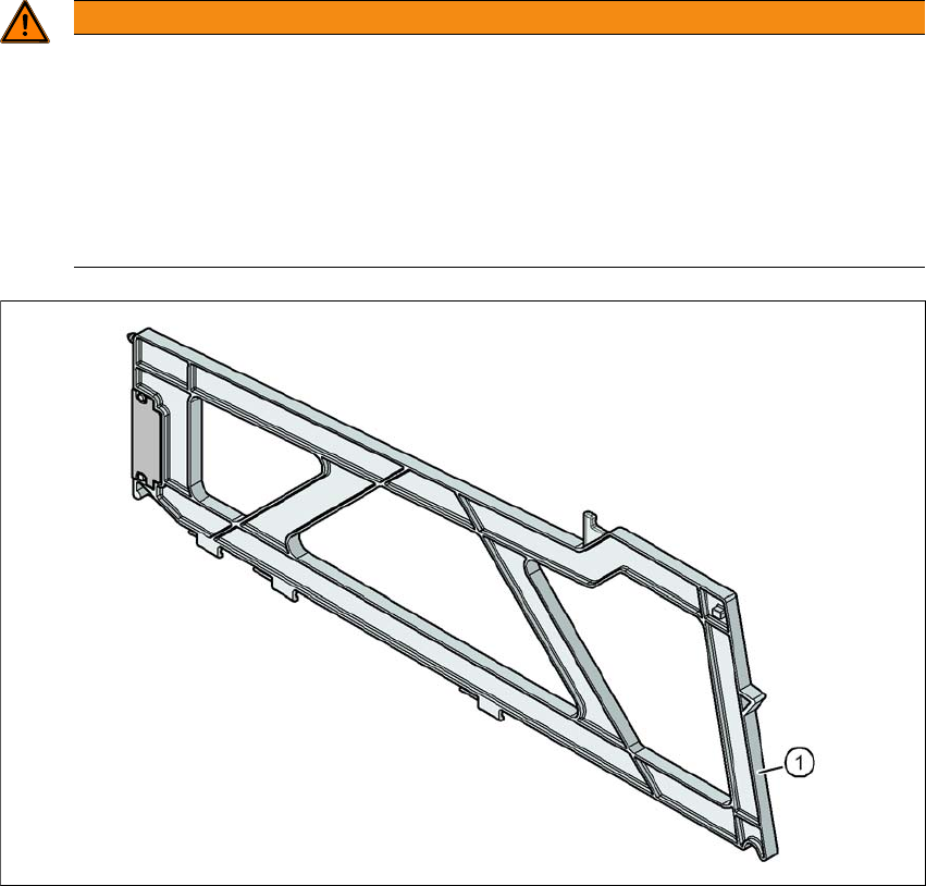
Fig. 2.6 - 10 Hand guard on the component trolley locations
2
(1) Dummy feeder SIPLACE X, item no. 00141226-xx
WARNING
Operatio nal
Operational safety by occupying every second location!
The operational safety of the component trolley in the SIPLACE X-Series S is ensured if
at least every second free location is occupied with a feeder module or hand guard (dum-
my feeder).
Insert a hand guard (dummy feeder) at every second free location.
Even when configuring a holder for waffle pack trays, secure every second location
with a hand guard.