00196378-0102_UM X-Feeder_EN.pdf - 第103页
Accessories Connecting the Tapes Tape Splicing Tool for SMD Tape Connections User Manual X Feeder M odules SIPLACE Family 103 See also 6.4.4 Consumable Mate rials Required [ ➙ 98] CAUTION Make sure t hat you do n ot to…
Accessories
Tape Splicing Tool for SMD Tape Connections Connecting the Tapes
102 User Manual X Feeder Modules SIPLACE Family
►Remove half of the protective foil from the special adhesive strips.
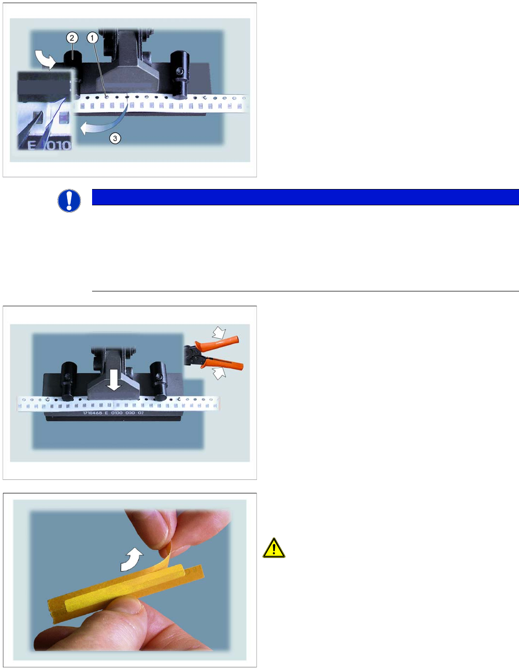
►Place the prepared beginning of the "new" tape onto
the pins (1), so that the tapes touch one another in
the center, over the splicing plate.
Make sure that the overlapping foil is lying on the
"old" tape end.
►Turn the swivelling latch to the front, to fix the
beginning of the tape into place.
NOTICE
The distance between the components at the splice point must be the same size as the normal
distance between components on the tape.
The ends of the new and old tape need to be cut at right angles for splicing, otherwise the tape
ends could shift, leading to tape conveyor malfunctions and finally to a machine standstill.
However, if there is a minor gap between the tape ends at the splice position, this will not have
a negative effect on the connection process.
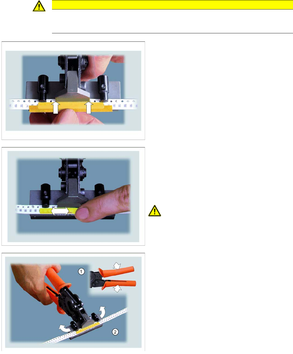
►Close the splice tool.
Press until the splice tool clicks for the third time. The
tape ends and the splicing plate will be riveted
together.
►Take the special adhesive strip with the correct width
for your component tape (see "6.4.6.4 Examples of
Correct Splice Connections" [ ➙ 105]).
CAUTION! Make sure that you ONLY use the
special adhesive tapes specified in Section for splicing.
NEVER use other adhesive tapes, such as normal sello-
tape!
Accessories
Connecting the Tapes Tape Splicing Tool for SMD Tape Connections
User Manual X Feeder Modules SIPLACE Family 103
See also
6.4.4 Consumable Materials Required [ ➙ 98]
CAUTION
Make sure that you do not touch the adhesive surface!
The adhesive tape could lose its adhesive strength and the cover foil of the new tape may not
be removed properly. This would then lead to a machine standstill.
►Place the adhesive strips down straight on the tape
ends and press to attach.
Make sure that the adhesive strips lie flat against the
head of the splice tool.
Use the adhesive tape to join the cover foil of the "old"
tape with that of the "new" tape.
►Carefully remove the second half of the cover foil from
the adhesive strip.
Make sure that you do not touch the adhesive sur-
face!
►Press the whole length of the adhesive strip down
onto the cover foil of the tape ends to make sure that
it attaches properly.
CAUTION! Make sure that the adhesive tape
does not protrude at the sides. Otherwise, it might get
caught in the feeder module. This would then lead to a
machine standstill.
►(1) Press the splice tool together until its head opens.
►(2) Press the swivelling latches on the left and right
towards the back.
You can now take the spliced tape out of the splice tool.
►Check the quality of the join.
Accessories
Tape Splicing Tool for SMD Tape Connections Connecting the Tapes
104 User Manual X Feeder Modules SIPLACE Family
Tapes with perforations on both sides
►Insert a splicing plate onto the two middle pins of the open splice tool, with the raised "spikes"
showing upwards.
►Take the tape which has been spliced on one side and place its splice point in the middle of the
splicing plate.
Make sure that all 4 pins engage in the tape perforations.
►Turn the swivelling latches on the left and right to the front, to fix the tape into place in this position.
►Press the splice tool together until its head opens.
►Turn the swivelling latches on the left and right towards the back.
You can now take the spliced tape out of the splice tool.
►Check the quality of the join.
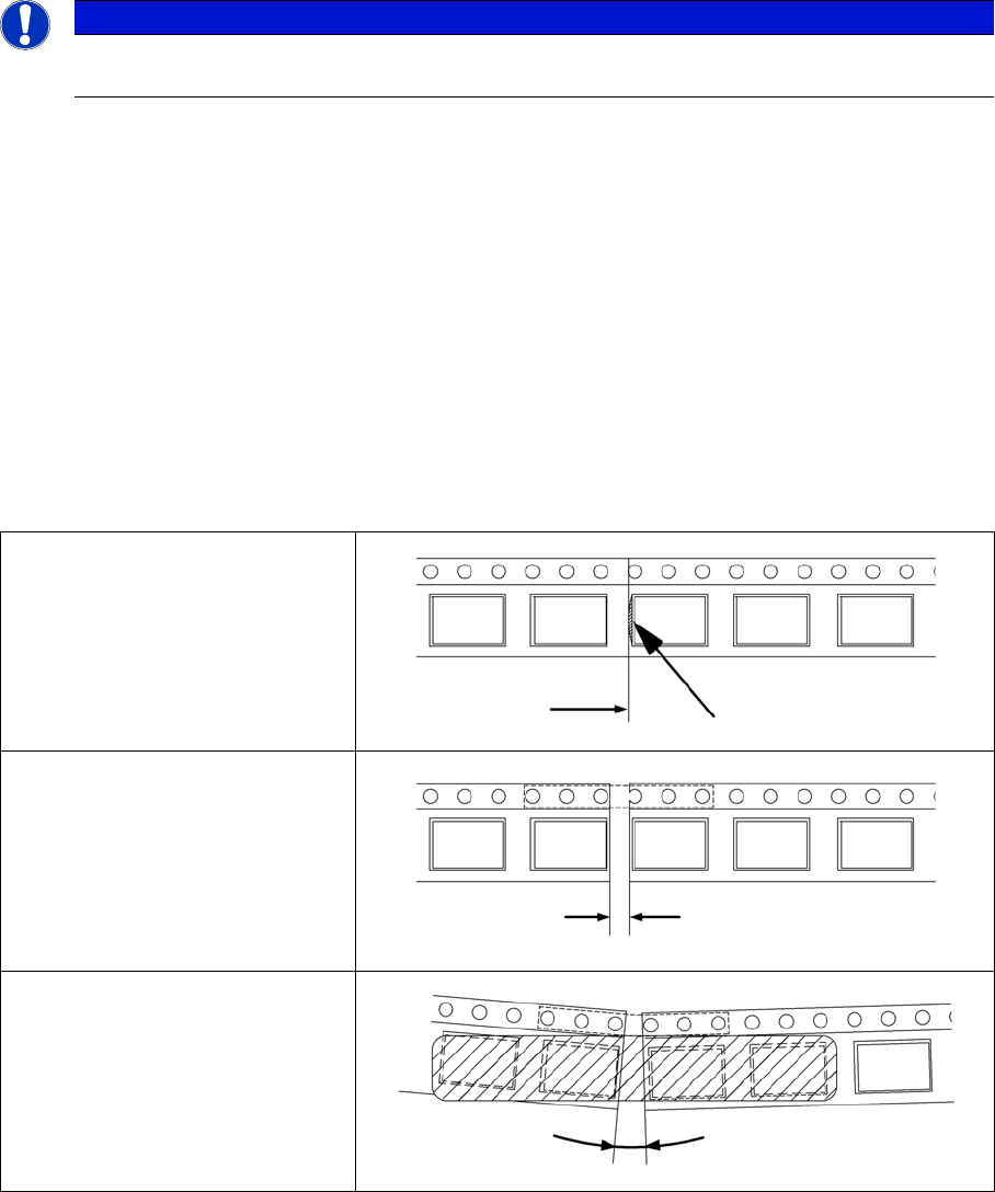
6.4.6.3 Checking the Join: Examples of Incorrect Connections
NOTICE
When using tapes with perforations on both sides, proceed as described above. Afterwards,
join the tape at the second perforation with another splicing plate.
The component pocket is cut open.
The gap between the tape ends is
too large.
The tape is folded at the splice
point.