00196378-0102_UM X-Feeder_EN.pdf - 第28页
Overview of X Feeder Modules Functions and Operating Contr ols Energy and Data Transfer 28 User Manual X Feeder Modules SIPLACE Family See also 5.2.1 Messages Sent by the Feeder Module [ ➙ 84] 5.2.2 Messages From Pro…

Overview of X Feeder Modules
Display at the Tape Feeder Modules Functions and Operating Controls
User Manual X Feeder Modules SIPLACE Family 27
Error Messages
Display text LED display Meaning Troubleshooting
None red, flashing The application software is
not present or faulty. Soft-
ware remains in the boot
loader.
Load the application software.
Handle
red The feeder module has been
logged in but the removal
handle has not yet been
pushed into the feeder mod-
ule.
Push the removal handle into the
feeder module.
Low Voltage
(Undervoltage)
orange 24 V supply voltage has not
increased the switching on
threshold after being
switched on.
Check the power supply.
Low Voltage
(Undervoltage)
red 24 V supply voltage has al-
ready exceeded the switch-
ing on threshold and has then
collapsed.
Check the power supply.
Feed Timeout
TransTimeout
(Timeout in tape
feeder cycle)
red Tape feeder cycle did not end
correctly within the specified
time (timeout for the "Feed"
function).
Is the tape reel jammed in the
container?
Is the component trapped in the
pickup area, between the tape
and the component window?
Eliminate the obstacle and restart
the conveyor using the arrow
keys of the operator panel. The
feeder module will finish the faulty
feed run and will return to its cor-
rect position.
Foil Torn
red Cover foil was not tensioned
within the prescribed time.
Probably, the foil has been torn.
Re-insert the cover foil and ten-
sion it.
Foil PeelErr
(Error when peeling
off the foil)
red Cover foil has not been cor-
rectly stripped off, although
the tape is being fed in.
The cover foil has probably been
trapped under the pickup window
and therefore has not been
stripped off properly.
Foil Jam
red The foil removal motor is
blocked.
Check, if the foil disposal rolls are
blocked by the cover foil.
EEP-WriteErr
(Error while backing
up data in the EEP-
ROM)
red The data backup has not
been performed correctly in
the EEPROM.
Since the position of the drive is
stored in the EEPROM, a refer-
ence run is necessary in these
cases. Acknowledge the error by
pressing the grey button at the
operator panel. After that, press
the yellow button to acknowledge
the prompt for a reference run
(see the reference run issue for
details).
EEP-ReadErr
(Error while reading
the EEPROM)
red The data from the EEPROM
have not been correctly read.
EEP-DataErr
(Error while backing
up the data in the
EEPROM)
red The data backup has not
been performed completely
in the EEPROM.
Overview of X Feeder Modules
Functions and Operating Controls Energy and Data Transfer
28 User Manual X Feeder Modules SIPLACE Family
See also
5.2.1 Messages Sent by the Feeder Module [ ➙ 84]
5.2.2 Messages From Process [ ➙ 89]
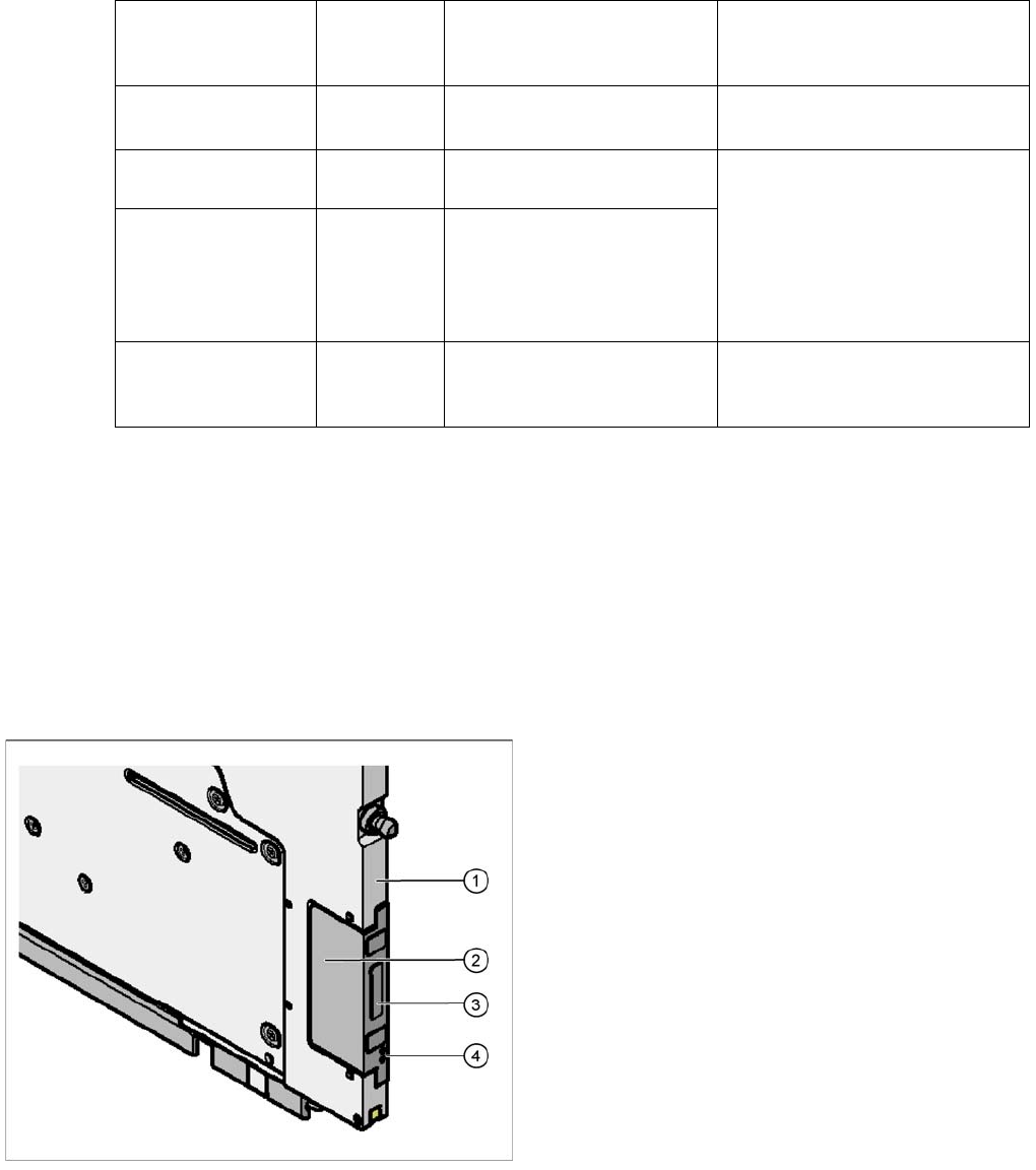
3.1.3 Energy and Data Transfer
The X-series feeder modules are equipped with an EDIF. EDIF is the abbreviation of energy and data
interface. The X-series feeder modules use a non-contact system for the electrical transmission of en-
ergy and communication of data. This enables you to place the feeder modules on the component table
or to remove them from the table, without the need to connect/disconnect cables.
Referenz o
Reference o
red The tape drive position infor-
mation is no longer available.
Remove the tape and press the
yellow button afterwards to start a
reference run.
CAN BusError
(CAN bus error)
red CAN bus error If a reset does not help, the feeder
needs repairing
ParNotSaved!
red The parameters are not
saved at all.
Default parameters are loaded
automatically, i.e. the most recent
operator settings are overwritten -
> If necessary, the settings (e.g.
pitch) will have to be made again.
If these errors occur too often, re-
place the control board.
ParWrongSave
red The parameters are wrong or
saved incompletely.
BootFlashErr
FlashDataErr
red Unable to correctly write data
in boot or application memo-
ry.
Replace the feeder module or
control board
Legend
1. Feeder module front
2. EDIF
3. Transformer core
4. Light conductor
Overview of X Feeder Modules
Energy and Data Transfer Functions and Operating Controls
User Manual X Feeder Modules SIPLACE Family 29
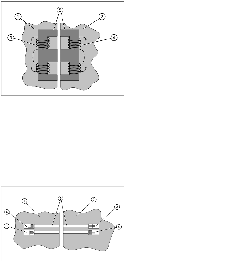
3.1.3.1 Energy Transmission
The electricity supply for the feeder module is supplied contact-less from the FCU (Feeder Control Unit)
to the module. This is done with the help of a split transformer. One half of the transformer is located in
the frame of the FCU, while the other half is in the feeder module. When the feeder module is placed on
the component table, the two halves of the transformer are exactly opposite one another. The floating
state of the EDIF in the feeder module ensures that the two sections of the transformer can be firmly
connected to one another without gaps.
Both transformer sections have coils. A.C. voltage from the machine side induces a magnetic field in the
transformer core, which then generates a.c. voltage on the feeder module side. This power is used to
supply the feeder module control unit and drives.
3.1.3.2 Data Transfer
The communication between placement machine and feeder module is also realized without contact.
The data is transmitted with the help of infrared (IR) light, through fibre optic cables. Two channels are
used for transmission; one channel for the signals from the FCU to the feeder module and one channel
for the signals from the module to the FCU. Each channel has its own transmitter (IR diode) and receiver
(IR photo sensor).
The data transferred is usually for feeder track synchronization commands; error messages; splice
sensor signals; ID numbers for setup verification or download data.
Legend
1. EDIF FCU
2. EDIF feeder module
3. FCU coil (primary side)
4. Feeder module coil (secondary side)
5. Split transformer ferrite core
Legend
1. EDIF FCU
2. EDIF feeder module
3. IR transmitter
4. IR receiver
5. Light conductor