00196378-0102_UM X-Feeder_EN.pdf - 第29页
Overview of X Feeder Modules Energy and Data Transfer Functions and Operating Controls User Manual X Feeder M odules SIPLACE Family 29 3.1.3.1 Energy Transmission The electricity supply for t he feeder modu le is supplie…
Overview of X Feeder Modules
Functions and Operating Controls Energy and Data Transfer
28 User Manual X Feeder Modules SIPLACE Family
See also
5.2.1 Messages Sent by the Feeder Module [ ➙ 84]
5.2.2 Messages From Process [ ➙ 89]
3.1.3 Energy and Data Transfer
The X-series feeder modules are equipped with an EDIF. EDIF is the abbreviation of energy and data
interface. The X-series feeder modules use a non-contact system for the electrical transmission of en-
ergy and communication of data. This enables you to place the feeder modules on the component table
or to remove them from the table, without the need to connect/disconnect cables.
Referenz o
Reference o
red The tape drive position infor-
mation is no longer available.
Remove the tape and press the
yellow button afterwards to start a
reference run.
CAN BusError
(CAN bus error)
red CAN bus error If a reset does not help, the feeder
needs repairing
ParNotSaved!
red The parameters are not
saved at all.
Default parameters are loaded
automatically, i.e. the most recent
operator settings are overwritten -
> If necessary, the settings (e.g.
pitch) will have to be made again.
If these errors occur too often, re-
place the control board.
ParWrongSave
red The parameters are wrong or
saved incompletely.
BootFlashErr
FlashDataErr
red Unable to correctly write data
in boot or application memo-
ry.
Replace the feeder module or
control board
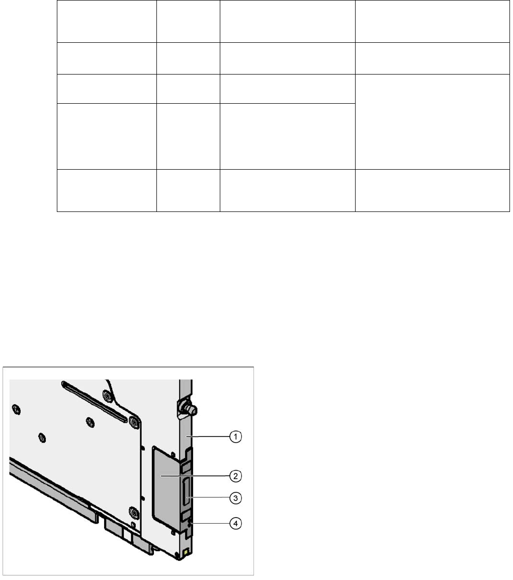
Legend
1. Feeder module front
2. EDIF
3. Transformer core
4. Light conductor
Overview of X Feeder Modules
Energy and Data Transfer Functions and Operating Controls
User Manual X Feeder Modules SIPLACE Family 29
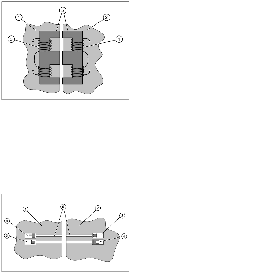
3.1.3.1 Energy Transmission
The electricity supply for the feeder module is supplied contact-less from the FCU (Feeder Control Unit)
to the module. This is done with the help of a split transformer. One half of the transformer is located in
the frame of the FCU, while the other half is in the feeder module. When the feeder module is placed on
the component table, the two halves of the transformer are exactly opposite one another. The floating
state of the EDIF in the feeder module ensures that the two sections of the transformer can be firmly
connected to one another without gaps.
Both transformer sections have coils. A.C. voltage from the machine side induces a magnetic field in the
transformer core, which then generates a.c. voltage on the feeder module side. This power is used to
supply the feeder module control unit and drives.
3.1.3.2 Data Transfer
The communication between placement machine and feeder module is also realized without contact.
The data is transmitted with the help of infrared (IR) light, through fibre optic cables. Two channels are
used for transmission; one channel for the signals from the FCU to the feeder module and one channel
for the signals from the module to the FCU. Each channel has its own transmitter (IR diode) and receiver
(IR photo sensor).
The data transferred is usually for feeder track synchronization commands; error messages; splice
sensor signals; ID numbers for setup verification or download data.
Legend
1. EDIF FCU
2. EDIF feeder module
3. FCU coil (primary side)
4. Feeder module coil (secondary side)
5. Split transformer ferrite core
Legend
1. EDIF FCU
2. EDIF feeder module
3. IR transmitter
4. IR receiver
5. Light conductor

Overview of X Feeder Modules
Functions and Operating Controls Energy and Data Transfer
30 User Manual X Feeder Modules SIPLACE Family
3.1.3.3 Troubleshooting, Maintenance and Cleaning
The X-series FCU also has automatic overload protection. If a feeder module causes an overload, the
monitoring device will respond by switching off the entire EDIF block in which the defective module is
located. After a certain cooling off period, the block will then be automatically reconnected.
Observe the following points, if a feeder module should malfunction in the placement machine:
▪ Check the entire front of the feeder module for components, foil residues, tape residues, contami-
nants or damage.
▪ Make sure that there are no components or contaminants on the transformer surfaces at the front of
the feeder module.
▪ Make sure that there are no components or other contaminants on the transformer surfaces of the
FCU.
▪ Make sure that the feeder module centering pin has been correctly inserted into the hole provided
on the CO table and that the feeder module has been pushed in as far as needed.
▪ Check that none of the feeder module parts are bent or protruding (e. g. loose screws).
▪ Check if the EDIF can freely be moved in the feeder module (floating state).
The EDIF should have a clearance of at least 1 mm.
If the EDIF can only be moved with difficulty or if it appears to be stuck, loosen the two slotted screws
on the feeder module EDIF and restore its ease of movement. Observe both the springs.
▪ Check the three rectangular ferrite core surfaces on the front of the EDIF for damage (breaks,
splintered edges).
▪ Check whether the ferrite cores of the feeder module protrude approx. 0.1 – 0.2 mm from the EDIF
plastic housing. These are flush fitted at the FCU end.
▪ Clean the data transfer optical system with a lint-free cloth, dipped in ethanol. Briefly wipe the front
end.
Aggressive cleaning agents or abrasive wiping movements with dry cloths can tarnish and dull the
front of the optical system. This would disrupt data transfer and could lead to feeder module malfunc-
tions.
▪ Check the fibre optic cable for damage (breaks, splintered edges).
CAUTION
Keep the EDIF clean.
Correct energy and data transmission is essential for a proper function of the feeder module
within the component table. The two halves of the EDIF must be placed very closely together
(no gaps) in order for sufficient energy to be transmitted. The light path for data transfer must
be free of contaminants or obstacles.
NOTICE
Maintenance and Cleaning
By regularly inspecting and cleaning, you reduce unexpected feeder downtime and increase
the productivity of your placement machines. These preventative measures include the follow-
ing tasks, which need to be performed at the prescribed intervals:
►Daily maintenance
Vacuum the feeder modules and remove loose components and contaminants from the
feed-in area.
Empty the foil bin completely.
►Cyclically recurring maintenance
Perform a visual check (e. g. once a year) and make sure that the feeder modules are
neither dirty nor damaged. If necessary, the relevant feeder module may need to be
cleaned or repaired..