00196378-0102_UM X-Feeder_EN.pdf - 第45页
Operating Tape Feeder Modules Inserting the Feeder Module into the Componen t Table User Manual X Feeder M odules SIPLACE Family 45 4 Operating Tape Feeder Modules 4.1 Inserting the Feeder Modu le into the Component Tabl…
Overview of X Feeder Modules
Overview of Types 88 mm X
44 User Manual X Feeder Modules SIPLACE Family
3.5.10 88 mm X
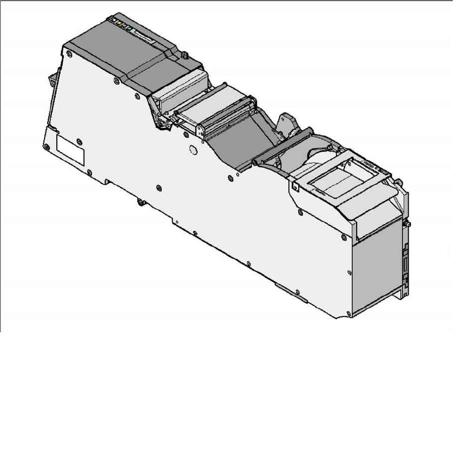
Tape feeder module 88 mm X
Item no. for the feeder module with splice sensor: 00141298-xx
Width: 105.2 mm
Used locations at the component table: 9
Conveyor pitch: 4 - 96 mm adjustable in 4 mm steps
Changeover time for the component tape: < 45 s
Changeover time for the offline setup feeder mod-
ule on the machine:
< 15 s
Operating Tape Feeder Modules
Inserting the Feeder Module into the Component Table
User Manual X Feeder Modules SIPLACE Family 45
4 Operating Tape Feeder Modules
4.1 Inserting the Feeder Module into the Component Table
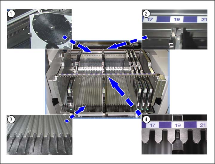
The following figure gives an overview of the component table elements that have to be considered for
correctly inserting the feeder modules.
Legend
1. Centering holes – front
2. Centering – front
3. Omega profile = Low feeder guide rails
4. Centering bar – rear
Operating Tape Feeder Modules
Inserting the Feeder Module into the Component Table
46 User Manual X Feeder Modules SIPLACE Family
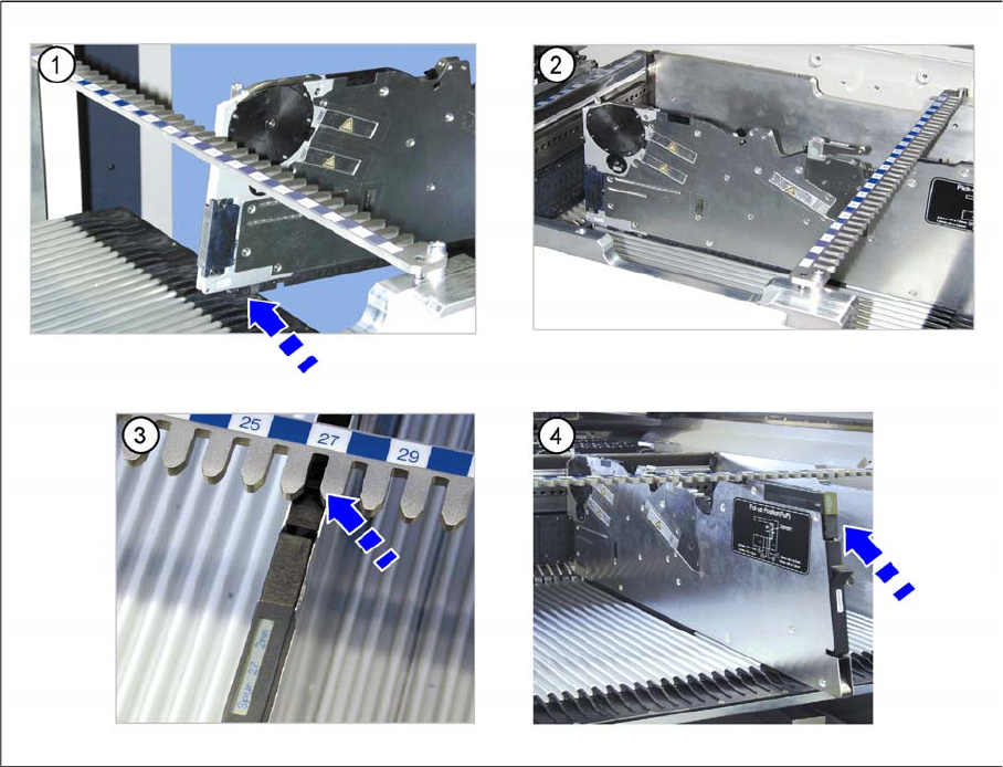
►(1) Place the feeder module with the front sliding guide onto the Omega profile of the component table
that is appropriate for the desired track.
►(2) Vertically push the feeder module forward on the guide until the front centering pin engages at the
component table.
►(3) Make sure that the rear centering pin stands in the correct recess of the rear centering bar that
corresponds to the front centering pin.
►(4) The login procedure is started. The status display at the rear end of the feeder module lights up
green when the login procedure has been completed successfully, when the feeder module is includ-
ed in the current setup and installed on the correct track.