00196378-0102_UM X-Feeder_EN.pdf - 第70页
Operating Tape Feeder Modules Using the Operator Panel Adjusting the Pickup Positions 70 User Manual X Feeder Modules SIPLACE Family 4.3.2.4 Pick-Up Positions for 16 - 88 mm X Feeder Modules There is only one pickup p os…
Operating Tape Feeder Modules
Adjusting the Pickup Positions Using the Operator Panel
User Manual X Feeder Modules SIPLACE Family 69
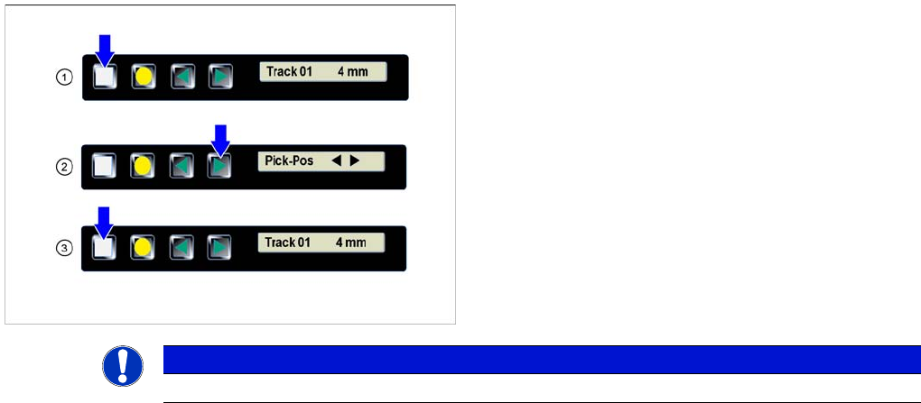
Setting the Pickup position
►(1) The display shows the start screen ("Track").
Press the Set button until the display shows
"Pick-Pos."
► (2) Press the Forwards button.
The tape is moved forwards in 2 mm steps. Press the
key several times, until the component center has
reached the pickup position.
►(3) Repeatedly press the Set button to return to the
start screen.
The setting is retained automatically.
NOTICE
The feeder will also return to the start screen, if no button is pressed for 1 minute.
Operating Tape Feeder Modules
Using the Operator Panel Adjusting the Pickup Positions
70 User Manual X Feeder Modules SIPLACE Family
4.3.2.4 Pick-Up Positions for 16 - 88 mm X Feeder Modules
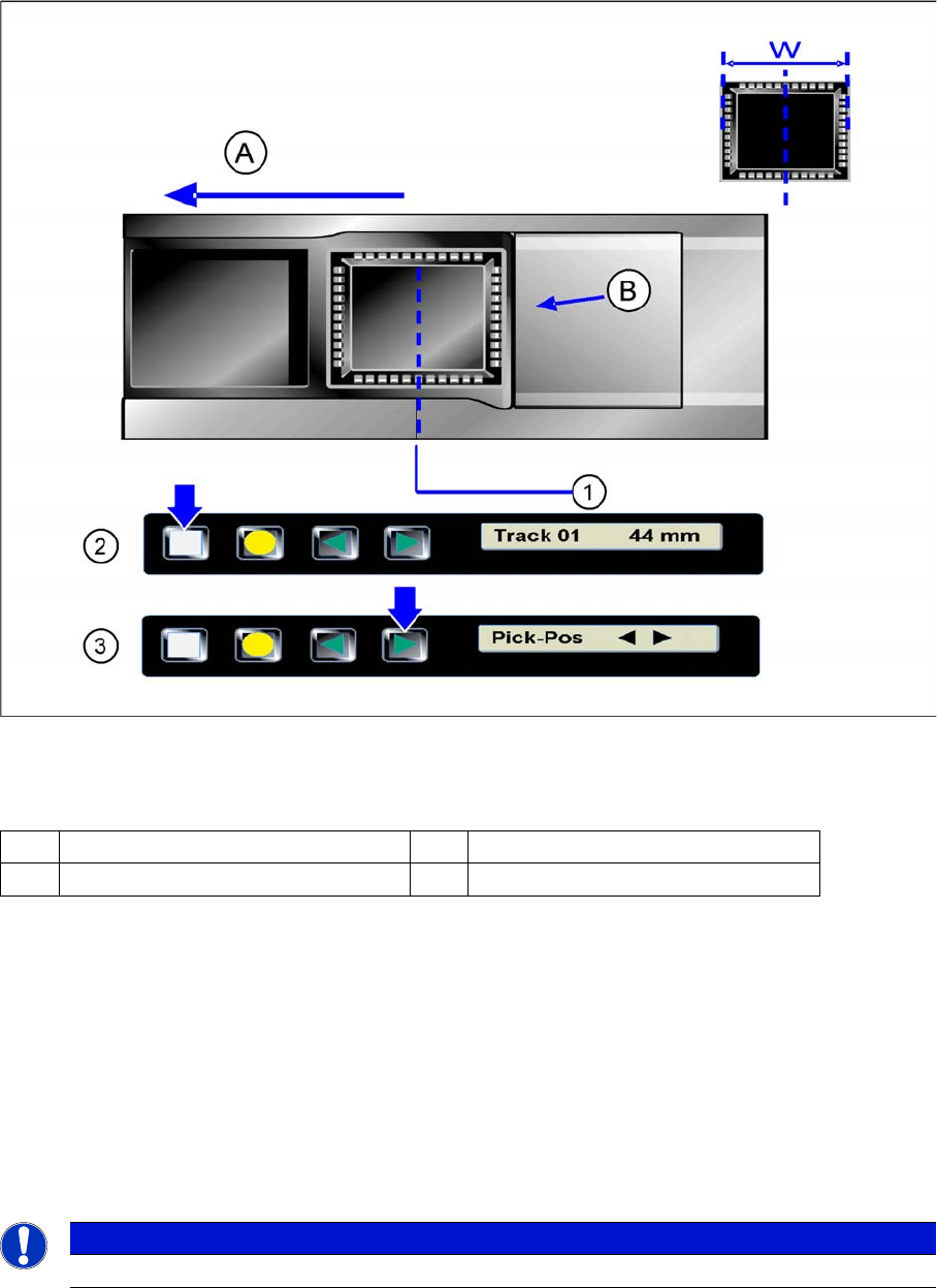
There is only one pickup position for 16 - 88 mm feeder modules. The tape material must be inserted or
set in such a way, that the center of the components to be processed is positioned in the center of the
pickup position.
Pickup position for 16 - 88 mm X feeder modules
Legend
Setting the Pickup position
►(1) Pickup position
►(2) The display shows the start screen ("Track")
.Press the Set button until the display shows "Pickup pos."
►(3) Press the Forwards button.
The tape is moved forwards in 2 mm steps. Press the key several times, until the component center
has reached the pickup position.
Repeatedly press the Set button to return to the start screen.
The setting is retained automatically.
A Direction of tape movement W Width of the components
B Foil removal edge
NOTICE
The feeder will also return to the start screen, if no button is pressed for 1 minute.
Operating Tape Feeder Modules
Setting the Pitch Using the Operator Panel
User Manual X Feeder Modules SIPLACE Family 71
4.3.3 Setting the Pitch
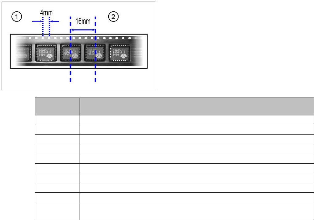
The pitches shown in the table can be set for the different X feeder module types. The pitch corresponds
to the distance between the centers of two adjacent components and must be set according to the size
of the components to be processed. The tape is moved by the set pitch in each step.
Legend
1. Hole distance
2. Pitch
Feeder mod-
ule
Possible pitches
8 mm 1, 2, 4, 8 mm
2x8 mm 1, 2, 4, 8 mm
12 mm 4, 8, 12, 16 mm
16 mm 4, 8, 12, 16, 20 mm
24 mm 4, 8, 12, 16, 20, 24, 28, 32 mm
32 mm 4, 8, 12, 16, 20, 24, 28, 32, 36, 40 mm
44 mm 4, 8, 12, 16, 20, 24, 28, 32, 36, 40, 44. 48, 52 mm
56 mm 4, 8, 12, 16, 20, 24, 28, 32, 36, 40, 44. 48, 52, 56, 60, 64 mm
72 mm 4, 8, 12, 16, 20, 24, 28, 32, 36, 40, 44. 48, 52, 56, 60, 64, 68, 72, 76, 80 mm
88 mm 4, 8, 12, 16, 20, 24, 28, 32, 36, 40, 44. 48, 52, 56, 60, 64, 68, 72, 76, 80, 84, 88, 92,
96 mm