00196378-0102_UM X-Feeder_EN.pdf - 第84页
Messages Messages for 8 - 88 mm Feeder Modules Messages Sent by the Feede r Module 84 User Manual X Feeder Modules SIPLACE Family 5.2 Messages for 8 - 88 mm Feeder Modules 5.2.1 Messages Sent by the Feeder Module 5.2.1.1…
Messages
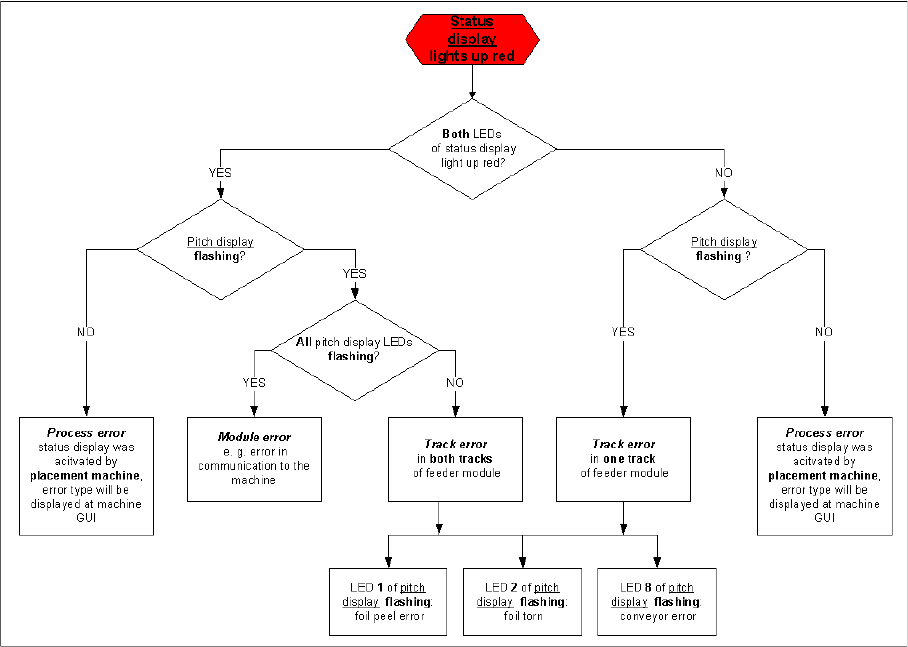
Flow Chart: Error Display on the Operator Panel Messages for 2x8 mm Feeder Modules
User Manual X Feeder Modules SIPLACE Family 83
5.1.3 Flow Chart: Error Display on the Operator Panel
The flow chart shows the logic according to which the errors are divided into the individual types. It
should help to identify an error.
Messages
Messages for 8 - 88 mm Feeder Modules Messages Sent by the Feeder Module
84 User Manual X Feeder Modules SIPLACE Family
5.2 Messages for 8 - 88 mm Feeder Modules
5.2.1 Messages Sent by the Feeder Module
5.2.1.1 Introduction
The following LCD and status displays are generated by the feeder module itself. The source of the error
is therefore usually the module state. The following tables show the LCD display text, the color and mode
of the status display, the cause and troubleshooting measures.
5.2.1.2 No Display
5.2.1.3 Initialization
5.2.1.4 Reference o
5.2.1.5 Software Reset
NOTICE
Through the constant further development of the station software, you may find that your feeder
module shows error texts which are not included in this list. In this case, please refer to the
Online Help function in the GUI and the station computer operating manual.
LCD, de:
LCD, en:
Status display: red, flashing rapidly
Cause: The feeder module is unable to start the application.
Solution: Reboot the application software. To do this, place the feeder module on the place-
ment machine and perform a software download in SITEST.
Comments: If the application software is not available or if it is defective, only the basic program
or so-called boot loader will be active. However, the display is unable to access
this and will remain dark.
LCD, de:
LCD, en:
Init Feeder
Init Feeder
Status display: off
Cause: The feeder module software is currently booting.
Solution: Wait (approx. 2 secs.)
LCD, de:
LCD, en:
Referenz o
Reference o
Status display: red
Cause: Tape drive position information is no longer available.
Solution: Remove the component tape (tape can be moved out by pressing the arrow
buttons or pulled out after raising the pickup window). Then perform a reference
run by pressing the "Foil" button.
LCD, de:
LCD, en:
SW Reset
SW Reset
Status display: red, flashing slowly
Cause: The automatic software reset is being performed e.g. after loading new para-
meters.
Solution: Wait (approx. 2 secs.)
Messages
Messages Sent by the Feeder Module Messages for 8 - 88 mm Feeder Modules
User Manual X Feeder Modules SIPLACE Family 85
5.2.1.6 Handle
5.2.1.7 Logging Off
5.2.1.8 Waiting for Log Off
5.2.1.9 Voltage Too Low 1
5.2.1.10 Voltage Too Low 2
LCD, de:
LCD, en:
Griff --->>
Handle --->>
Status display: Red
Cause: The feeder module has been logged in but the removal handle has not yet been
engaged (pushed in).
Solution: Push in the handle until it engages.
Comments: If the handle does not engage properly, send the feeder module to ASM Assembly
Systems for repair.
LCD, de:
LCD, en:
Abmelden
Logging Off
Status display: lights up red briefly
Cause: The feeder module is logging off at the FCU. This display will normally only appear
briefly and you usually won't see it. If it is clearly visible, there is probably a mal-
function.
Solution: Error in the FCU, on fibre optic cable, CAN bus
LCD, de:
LCD, en:
Wait Log Off
Wait Log Off
Status display: orange
Cause: The feeder module is logging off at the FCU. This display will normally only appear
briefly and you usually won't see it. If it is clearly visible, there is probably a mal-
function.
Solution: Error in the FCU, on fibre optic cable, CAN bus
LCD, de:
LCD, en:
Spg. niedrig
Low Voltage
Status display: orange
Cause: 24 V supply voltage has not reached the switching on threshold after being
switched on.
Solution: Check voltage supply of the component table, check EDIF
LCD, de:
LCD, en:
Spg. niedrig
Low Voltage
Status display: red
Cause: 24 V supply voltage has exceeded the switching on threshold and has then
collapsed.
Solution: Check voltage supply of the component table, check EDIF