00196378-0102_UM X-Feeder_EN.pdf - 第96页
Accessories Energy and Data Interface (Single Slot EDIF) for X Fe eder Modules Description 96 User Manual X Feeder Modules SIPLACE Family 6.3 Energy and Data Interface (Si ngle Slot EDIF) for X Feeder Module s 6.3.1 Desc…
Accessories
Feeder Module Adapter for the X Series with vibration feeder Feeder Module Adapter for the X Series
User Manual X Feeder Modules SIPLACE Family 95
6.2.2 Feeder Module Adapter for the X Series with vibration feeder
6.2.3 Feeder Module Adapter for the X Series with Reject Conveyor Module
NOTICE
The scope of delivery of the feeder module adapter for the X series also includes an adapter
plate:
Component heights up to 16.5 mm are processed with MIT adapter plate.
Component heights between 16.5 mm and 25 mm are processed WITHOUT adapter plate.
Feeder module adapter for the X series with vibration
feeder
Item no. 00141305-xx
Legend
1. Adapter for feeder modules of the X series
[00141305-xx]
2. Adapter plate 16.5 mm (included in scope of delivery)
3. Vibration feeder
NOTICE! Observe the correct switch setting on
the X feeder adapter.
According to the model, select switch setting 1, 2 or 3 for
the vibration feeder.
Feeder module adapter for the X series with reject con
-
veyor module
Item no. 00141308-xx
Legend
1. Adapter for feeder modules of the X series
[00141305-xx]
2. Adapter plate for reject conveyor [00141308-xx]
3. Reject Conveyor
NOTICE! Observe the correct switch setting on
the X feeder adapter.
Use setting 5 for the reject conveyor.
Accessories
Energy and Data Interface (Single Slot EDIF) for X Feeder Modules Description
96 User Manual X Feeder Modules SIPLACE Family
6.3 Energy and Data Interface (Single Slot EDIF) for X Feeder
Modules
6.3.1 Description
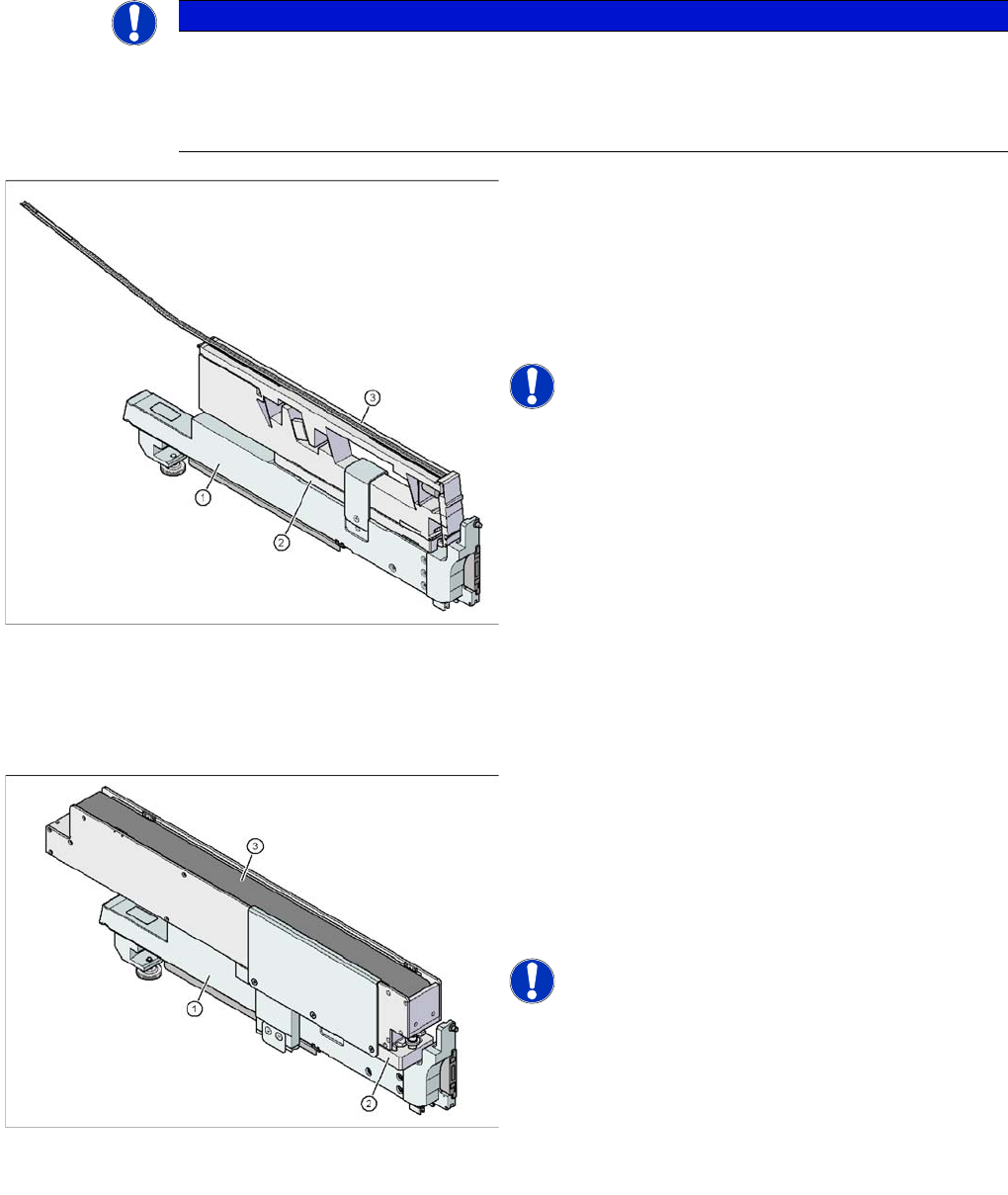
By means of the energy and data interface X feeder modules can be put into operation outside the
machine and the pre-setup location. The interface consists of an Omega profile for taking in and guiding
the feeder modules. Like on the component trolley the feeder module is placed on the Omega profile
with its sliding guides and pushed forwards until the front centering pin completely immerges into the
hole. The locking latch locks the feeder module in this position.
For removing the feeder module press the unlocking button. The locking latch is pressed down and
releases the feeder module. Foldout feet stabilize the position of the energy and data interface, namely
for broad feeder modules.
The electronic housing contains the control electronic for the energy and data interface. The operator
panel consists of a start and and stop button as well as two LEDs for the status display. Communication
with the PC is carried out via the data cable. The power supply cable is connected to the power supply
which is contained in the scope of delivery.
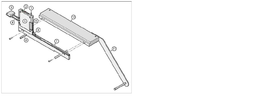
6.3.2 Usage
The energy and data interface is used for checking, maintaining and repairing X feeder modules. In
addition, it can be used for offline setups in the PCB production. For this purpose, the energy and data
interface is fitted on the base plate. The reel holder is also mounted to the base plate. When the compo-
nent tape is inserted you can either check or change the values for pitch, pickup position and transport
speed.
A detailed operating manual describes the handling of the interface and the corresponding service
works.
6.3.3 Scope of Delivery
▪ Single Slot EDIF
▪ Power supply, 100 - 120 / 200 - 240 V~, +30 V-, 4.3 A
▪ Base plate with reel arm
▪ Operating manual
Energy and data interface for X feeder modules
Item no. 00141247-xx
Legend
1. Unlocking button for releasing the locking latch
2. Operator panel
3. Data cable
4. Power supply cable
5. Electronic housing
6. Foldout feet
7. Omega profile for guiding the feeder modules
8. Locking latch
9. Hole for the front centering pin of the feeder module
10. Base plate
11. Reel holder
Accessories
Area of Use Tape Splicing Tool for SMD Tape Connections
User Manual X Feeder Modules SIPLACE Family 97
6.4 Tape Splicing Tool for SMD Tape Connections
6.4.1 Area of Use
The splice tool enables you to splice on a new tape for refilling components on tapes without causing a
machine standstill.
The splicing procedure takes place outside the working area of the SIPLACE placement machine which
is secured with protective switches.
When splicing components on tapes, you connect the virtually finished paper or blister tape in the feeder
with the beginning of a new tape.
The splice tool functions like a crimping tool. It enables you to "rivet" the underside of the tape, thereby
connecting the "old" and "new" tapes with one another. A special adhesive strip on the upper side of the
tape connects the cover foil.
When correctly connected, the tape ends are joined together precisely to the grid. The tape - with its
transition point - can then be seamlessly transported into the feeder and the foil can be stripped off as
usual.
The splice tool can be used to splice all blister or paper tapes.
Tapes WITHOUT cover foil (surf tapes) are NOT spliced together.
Item No. 02102987-xx
NOTICE! A description of how to splice tapes is
also available as a poster for your production site: Job
Poster "", Item No. 00192460-xx
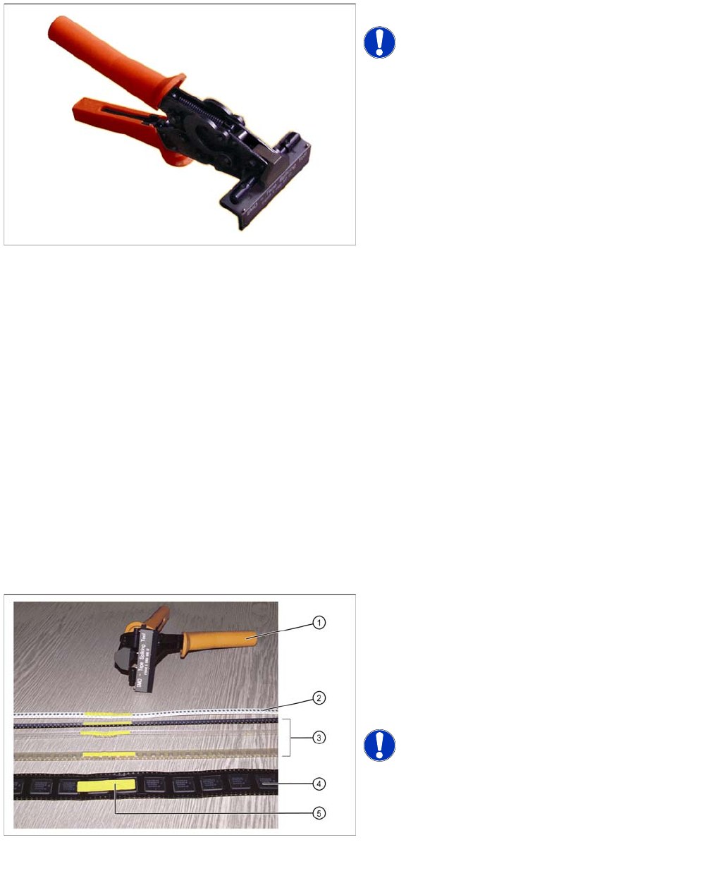
Splicing tapes
Splice tool and complete splicing of paper and blister
tapes (with single-sided and double-sided perforations
Legend
1. Splice tool
2. 8 mm paper tape
3. Blister tapes with perforations on one side
4. Blister tape with perforations on both sides
5. Complete SMD tape splicing
NOTICE! The splice tool can be used easily by
both right and left-handed persons.