H02 Head Operation Manual R4a.pdf.pdf - 第6页
Page 6 of 9 4.3. Using custom nozzles in production When using standard nozzles, it is possible to have both holders perform pre-rotation in a single pick and place cycle regardless of the pl acing angle. Therefore, pre-…

Page 5 of 9
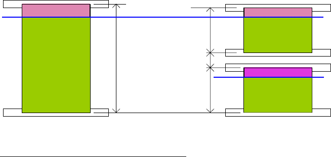
height (includes part height and pin length)
• A data check error occurs if the H02 head dedicated short nozzles or custom nozzles of a
similar length are not set when there are parts taller than 17.4 mm in height (includes part
height and pin length).
4.2. Parts taller than 21.5 mm (part height and pin length) are placed using mechanical
chucks
The H02 head can place parts with a height of 25.4 mm. When parts taller than 21.5 mm
(including part height and pin length) are placed with a mechanical chuck, a H02 head
dedicated short mechanical chuck must be used.
1. Job settings
H02 head dedicated short mechanical chucks are standard mechanical chucks and have to
be specified in the [Nozzle Name] setting. Select short mechanical chucks for the H02 head
in the [Nozzle Changer Setup].
2. Optimizing the job
Optimize the job.
3. Changeover and production
Set the H02 head dedicated short mechanical chuck in the nozzle station and then begin
production. If the mechanical chuck is not set, guidance is displayed to inform the operator to
set the correct mechanical chuck. Follow the guidance if it appears on the operation panel.
Cautions
• H02 head dedicated short mechanical chucks cannot be used with the H01 head.
• A data check error occurs if the H02 head dedicated short mechanical chucks are
specified in the [Nozzle Name] setting for parts 21.5 mm or less in height (includes part
height and pin length)
• A data check error occurs if the H02 head dedicated short mechanical chucks are not
specified in the [Nozzle Name] setting for part sizes taller than 21.5 mm (includes part
height and pin length).

Page 6 of 9
4.3. Using custom nozzles in production
When using standard nozzles, it is possible to have both holders perform pre-rotation in a
single pick and place cycle regardless of the placing angle. Therefore, pre-rotation is always
used irrespective of the [Do Prerotation] setting in the shape data.
When using custom nozzles, it may not be possible to have both holders perform pre-rotation
in a single pick and place cycle because it depends on the placing angle. When this occurs,
split the pick and place cycle so that the pre-rotation setting can be turned on or off in the job.
The default setting is “Yes”. Change this to “No” if you want to give cycle time priority.
Fuji Flexa settings
[Shape Data]-[Shape Process]-[Process]-[Do Prerotation for Custom Nozzle]
When using custom nozzles, this setting determines whether the part is rotated to the angle
for placement before vision processing.
Specify [Yes] or [No]
4.4. Using the tray remover in production
Usable tray removers
H02 compatible remover (AA6GX00)
Tray removers that cannot be used
Initial type remover (AA3WH09)
Remover with modified pickup (AA3WH10)
Use the tray unit-L with the H02 compatible remover.
An error (????4716) will occur after pushing START, if the tray unit-L has an initial type
remover or a modified pickup remover,
Page 7 of 9
5. Cautions for the H02 Head during Production
5.1. Y-axis movement restriction
Holder B can only move so far in the Y-direction due to mechanical limitations. This limitation
is shown below.
5.1.1. Placement area for the NXT
280
280
47
610
H02 holder B limit
Area where holder B cannot place parts
Double conveyor – 7 mm from the far side of the panel
Single conveyor – 10 mm from the far side of the panel
Only holder A can place parts in this area. Therefore, the Fuji Flexa optimizer ensures that
parts are placed in this area using holder A. However, if the part is too large to be placed with
holder A then it cannot be placed in this area. A data check error will result and a H01 head
should be used in this case.