H02 Head Operation Manual R4a.pdf.pdf
Page 1 of 9 H02 Head Operation Manual 1. Introduction ................................................................................................................. 2 2. Required Items ................................…

Page 1 of 9
H02 Head Operation Manual
1. Introduction .................................................................................................................2
2. Required Items ............................................................................................................2
3. H02 Head Specifications .............................................................................................3
4. Production Examples...................................................................................................4
4.1. Parts larger than 17.4 mm (part height and pin length) are placed using nozzles .........4
4.2. Parts larger than 21.5 mm (part height and pin length) are placed using mechanical
chucks ......................................................................................................................... 5
4.3. Using custom nozzles in production ..............................................................................6
4.4. Using the tray remover in production .............................................................................6
5. Cautions for the H02 Head during Production .............................................................7
5.1. Y-axis movement restriction ........................................................................................... 7
5.1.1. Placement area for the NXT ....................................................................................... 7
5.2. Single nozzle operation..................................................................................................8
5.3. Using the AVL function in production .............................................................................8
6. Considerations when changing from the H01 head to a H02 head..............................9
6.1. Capabilities of the H01 head that are not possible with the H02 head...........................9
6.2. Shared items for the H01 and H02 heads and new items required by the H02 head ....9
6.3. Others............................................................................................................................9
Page 2 of 9
1. Introduction
The H02 head is now supported as a standard Fuji item. The H02 head has two holders and
the same placing accuracy as the H01 head. This manual contains cautions for using the H02
head in production as well as considerations when changing from a H01 head to a H02 head.
Furthermore, the Fuji Flexa settings [Pin length] and [Part height] are listed below.
• Pin length [Shape Data]-[Shape Process]-[Body]-[Location Pin Length]
• Part height [Shape Data]-[Shape Information]-[Body]-[Height]
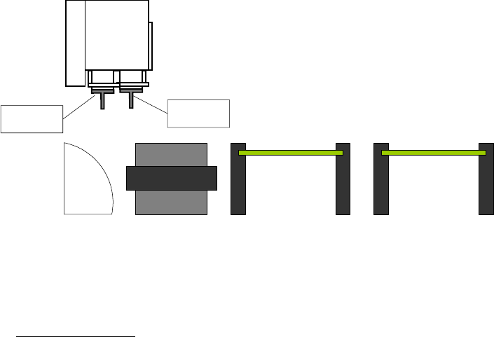
Holder A and B are shown below in the drawing.
2. Required Items
The following items are required to perform production with the H02 head.
Required software
• NXT application software V4.50 and later
• Fuji Flexa V4.1.0 and later
Holder B
Holder A

Page 3 of 9
3. H02 Head Specifications
Item Details
Usable nozzles H01 head standard nozzles, custom nozzles, mechanical chucks
H02 head dedicated short nozzles, short mechanical chucks
Nozzle station Same as used for the H01 head
Part size 1608 to 74 x 74 mm (32 x 180 mm)
Note: Holder A is 32 x 120 mm
Part height 25.4 mm (1)
Production
throughput
M3 4800 CPH
M3S 4800 CPH
M6 4400 CPH
M6S 4900 CPH
Note 1:
• The height is up to 6 mm (the pin length and part height added together) if the nozzle size X or Y is 36
mm or more for custom nozzles.
• The height is up to 21.5 mm (the pin length and part height added together) if the nozzle size X or Y is 36
mm or more for mechanical chucks.