00193368-02.pdf - 第12页
SIPLACE GEM for S25HM, S27HM, HS50 , HS60 SW Version GEM 503.02 HOST Inter fac e Manual Page 12 of 243 ©Siemens AG, all rights reser ved Equipment The SIPLACE S25HM, S27HM or SI PLACE HS50, HS60 with GEM/SECS II-Interfac…

SIPLACE GEM for S25HM, S27HM, HS50, HS60 SW Version GEM 503.02
HOST Interface Manual
©Siemens AG, all rights reserved page 11 of 243
1.5 GEM Compliance Statement
GEM COMPLIANCE STATEMENT
FUNDAMENTAL GEM REQUIREMENTS IMPLEMENTED
COMPLIANT
State Models 3Yes 3 Yes
Equipment Processing States 3 Yes 3 Yes
S1,F13/F14 Scenario 3 Yes 3 Yes
Event Notification 3 Yes 3 Yes
On-line Identification 3 Yes 3 Yes
Error Messages 3 Yes 3 Yes
Control (Operator Initiated) 3 Yes 3 Yes
Documentation 3 Yes 3 Yes
ADDITIONAL CAPABILITIES IMPLEMENTED COMPLIANT
Establish Communications 3 Yes 3 Yes
Dynamic Event Report Configuration 3 Yes 3 Yes
Variable Data Collection 3 Yes 3 Yes
Trace Data Collection 3 Yes 3 Yes
Status Data Collection 3 Yes 3 Yes
Alarm Management 3 Yes 3 Yes
Remote Control (1) 3 Yes ¨ No
Equipment Constants 3 Yes 3 Yes
Process Program Management (2) ¨ No ¨ No
Material Movement 3 Yes 3 Yes
Equipment Terminal Services 3 Yes 3 Yes
Clock 3 Yes 3 Yes
Limits Monitoring 3 Yes 3 Yes
Spooling 3 Yes 3 Yes
Control (Host Initiated) 3 Yes 3 Yes
(1) : Remote commands, only Start and Stop are available in this stage.
(2) : Process Program Management is not implemented until a later stage.
1.6 Terminology
The following terms are used throughout the document to refer to the various entities
interfacing with the SIPLACE:
SIPLACE GEM for S25HM, S27HM, HS50 , HS60 SW Version GEM 503.02
HOST Interface Manual
Page 12 of 243 ©Siemens AG, all rights reserved
Equipment The SIPLACE S25HM, S27HM or SIPLACE HS50, HS60 with GEM/SECS
II-Interface
Operator The person who physically has access to the equipment’s material port(s)
and control panel. This is the person who is operating the SIPLACE.
Host The computer which is connected to the equipment via the SECSII-interface
1.7 Machine Areas
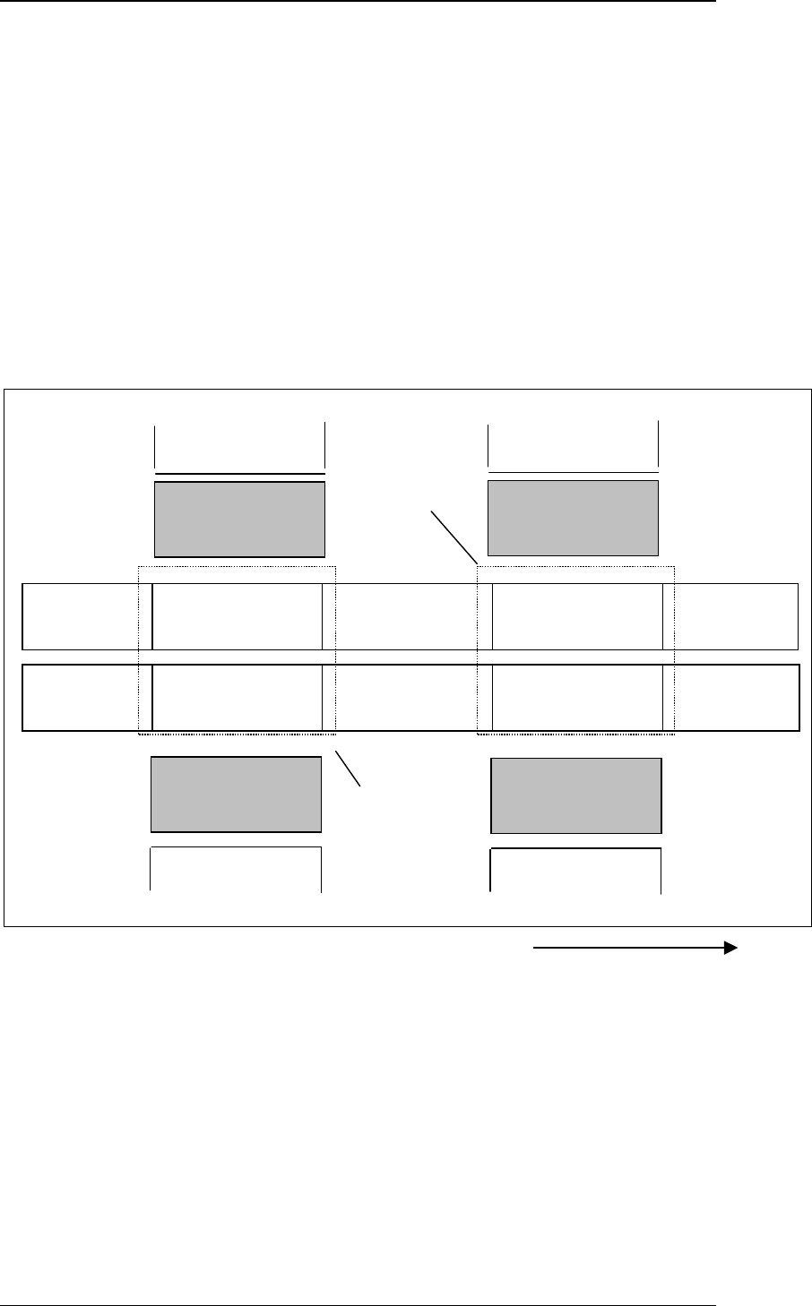
1.7.1 Machine Areas of a SIPLACE HS50 HS60 Machine
The figure below provides a diagrammatic overview of the individual areas of a
SIPLACE HS-50 placement station.
TWIN-Input
conveyor
TWIN-First
Processing
conve
y
o
r
TWIN-Output
conveyor
Input
conveyor
First Processing
conveyor
Output
conveyor
Direction of transport
Conveyor 2
(left)
Conveyor 1
(right)
Gantry 3
Revolverhead 3
Gantry 2
Revolverhead 2
Location
3
Location
2
TWIN-Inter-
mediate conveyor
TWIN-Second
Processing
conve
y
o
r
Intermediate
conveyor
Second Processing
conveyor
Gantry 4
Revolverhead 4
Location
4
Gantry 1
Revolverhead 1
Location
1
Processing 1
Area
Processing 2
Area
SIPLACE GEM for S25HM, S27HM, HS50, HS60 SW Version GEM 503.02
HOST Interface Manual
©Siemens AG, all rights reserved page 13 of 243
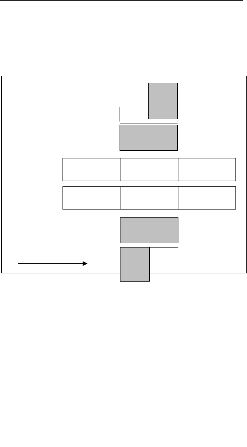
1.7.2 Machine Areas of a SIPLACE S25HM S27HM Machine
The layout of the feeder locations of the S25HM, S27HM machine depends on the
configuration of the individual machine. If there is an MTC on one side of the machine, the
locations are divided. Otherwise they are grouped into one location. The following figures
illustrate the individual variants.
The figures shows the machine areas of an S25HM, S27HM with dual conveyor and 2
MTCs.
The conveyor belts are divided into 3 areas. There are 4 feeder locations.
TWIN-Input
conveyor
TWIN-First
Processing
conve
y
o
r
TWIN-Output
conveyor
Input
conveyor
First Processing
conveyor
Output
conveyor
Direction of transport
Conveyor 2 (left)
Conveyor 1 (right)
Gantry 1
Revolverhead 1
Gantry 2
Revolverhead 2
Location
3
MTC
Location
4
Location
2
Location
1
MTC