00193368-02.pdf - 第13页
SIPLACE GEM for S25HM, S27HM, HS50, HS60 SW Version GEM 503.02 HOST Inter fac e Manual ©Siemens AG, all rights reserved page 13 of 243 1.7.2 Machine A reas of a SIPL A CE S25HM S27HM M achine The layout of the feeder loc…
SIPLACE GEM for S25HM, S27HM, HS50 , HS60 SW Version GEM 503.02
HOST Interface Manual
Page 12 of 243 ©Siemens AG, all rights reserved
Equipment The SIPLACE S25HM, S27HM or SIPLACE HS50, HS60 with GEM/SECS
II-Interface
Operator The person who physically has access to the equipment’s material port(s)
and control panel. This is the person who is operating the SIPLACE.
Host The computer which is connected to the equipment via the SECSII-interface
1.7 Machine Areas
1.7.1 Machine Areas of a SIPLACE HS50 HS60 Machine
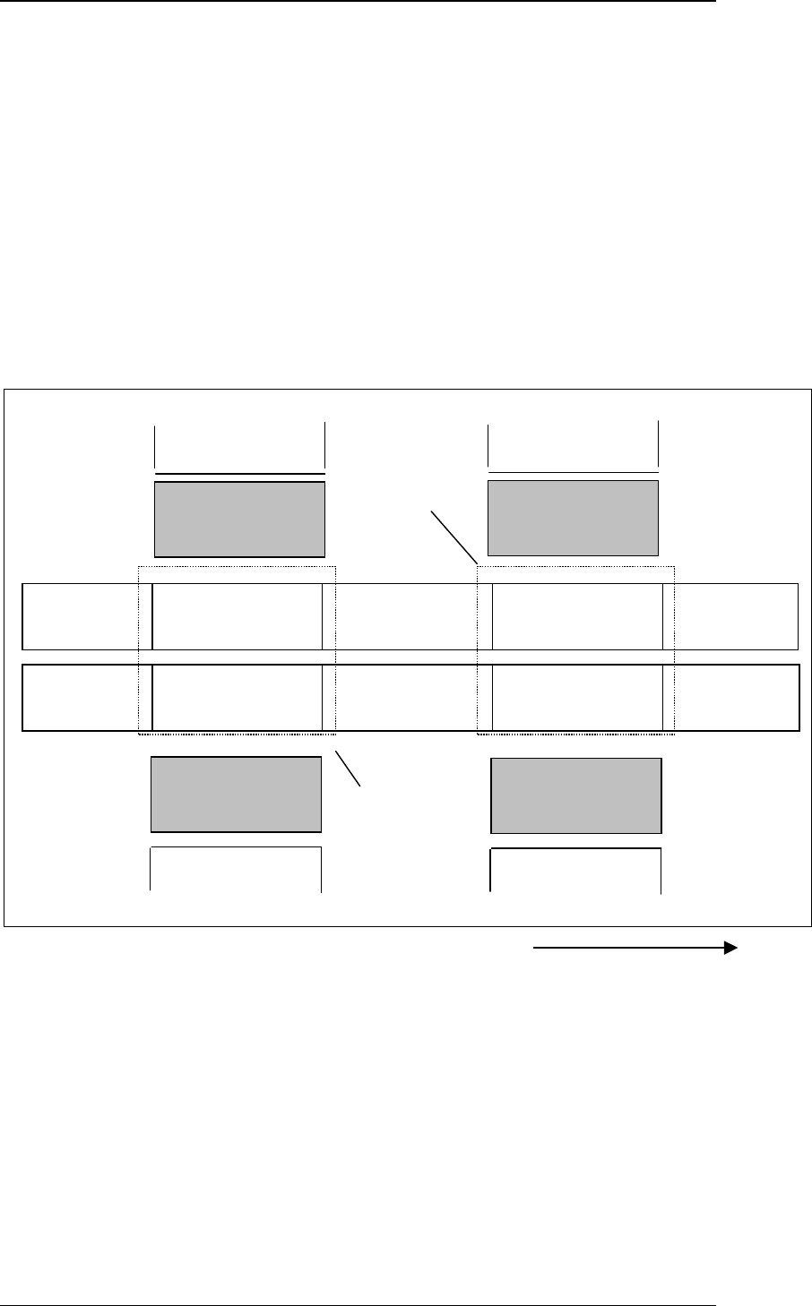
The figure below provides a diagrammatic overview of the individual areas of a
SIPLACE HS-50 placement station.
TWIN-Input
conveyor
TWIN-First
Processing
conve
y
o
r
TWIN-Output
conveyor
Input
conveyor
First Processing
conveyor
Output
conveyor
Direction of transport
Conveyor 2
(left)
Conveyor 1
(right)
Gantry 3
Revolverhead 3
Gantry 2
Revolverhead 2
Location
3
Location
2
TWIN-Inter-
mediate conveyor
TWIN-Second
Processing
conve
y
o
r
Intermediate
conveyor
Second Processing
conveyor
Gantry 4
Revolverhead 4
Location
4
Gantry 1
Revolverhead 1
Location
1
Processing 1
Area
Processing 2
Area
SIPLACE GEM for S25HM, S27HM, HS50, HS60 SW Version GEM 503.02
HOST Interface Manual
©Siemens AG, all rights reserved page 13 of 243
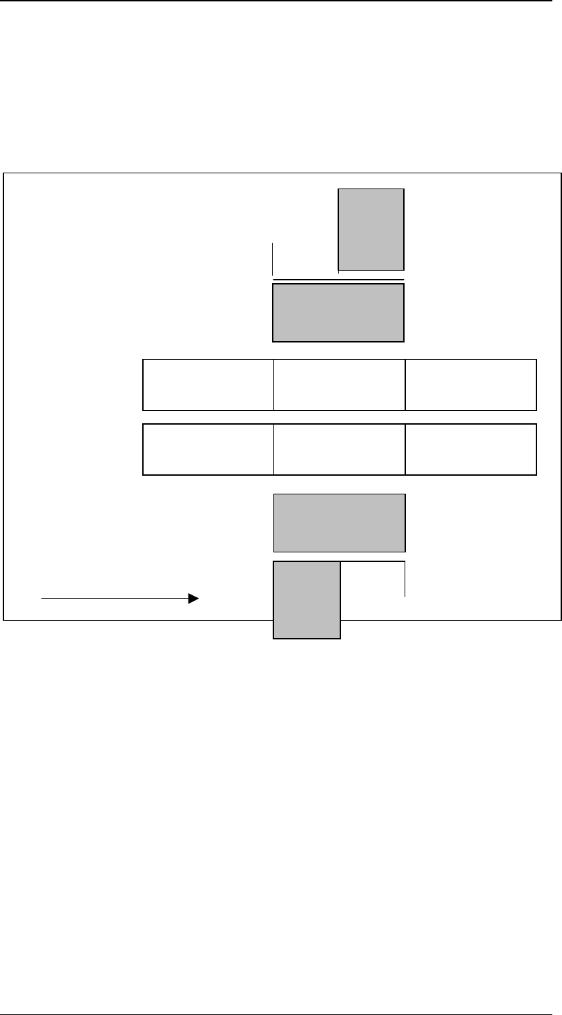
1.7.2 Machine Areas of a SIPLACE S25HM S27HM Machine
The layout of the feeder locations of the S25HM, S27HM machine depends on the
configuration of the individual machine. If there is an MTC on one side of the machine, the
locations are divided. Otherwise they are grouped into one location. The following figures
illustrate the individual variants.
The figures shows the machine areas of an S25HM, S27HM with dual conveyor and 2
MTCs.
The conveyor belts are divided into 3 areas. There are 4 feeder locations.
TWIN-Input
conveyor
TWIN-First
Processing
conve
y
o
r
TWIN-Output
conveyor
Input
conveyor
First Processing
conveyor
Output
conveyor
Direction of transport
Conveyor 2 (left)
Conveyor 1 (right)
Gantry 1
Revolverhead 1
Gantry 2
Revolverhead 2
Location
3
MTC
Location
4
Location
2
Location
1
MTC
SIPLACE GEM for S25HM, S27HM, HS50 , HS60 SW Version GEM 503.02
HOST Interface Manual
Page 14 of 243 ©Siemens AG, all rights reserved
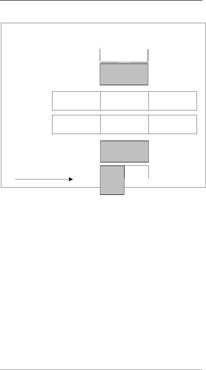
This figure shows an S25HM, S27HM machine with 1 MTC.
If the machine has only 1 MTC, there is one divided feeder location and one undivided
feeder location. The MTC can be on location 1 or 3.
If the MTC is on location 1, locations 1 and 2 are on the RH side and there is a shared
feeder location on the LH side (see illustration).
If the MTC is on the LH side, locations 3 (MTC) and 4 are on the LH side and a there is a
shared location 1 on the RH side.
TWIN-Input
conveyor
TWIN-First
Processing
conve
y
o
r
TWIN-Output
conveyor
Input
conveyor
First Processing
conveyor
Output
conveyor
Direction of transport
Conveyor 2 (left)
Conveyor 1 (right)
Gantry 1
Revolverhead 1
Gantry 2
Revolverhead 2
Location
3
Location
2
Location
1
MTC