00194579-0202.pdf - 第45页
Retrofit instructions Wide board 242 / 508 mm SIPLACE HS-60 / D4 08/2006 Edition 47 2.6.4 Reducing the minimum tr aveling range for gantry 4 : Reduce the minimum traveling range of gantry 4 by 25 000. : Recalibrate the m…
Retrofit instructions Wide board 242 / 508 mm SIPLACE HS-60 / D4
08/2006 Edition
46
The necessary offsets are read from a new table in the machine database. 2
The moved position is also transferred to the machine configuration (config.ma). Only then is a
change in the "Position of stationary side wall“ conveyor configuration to "Wide“ enabled. 2
2.6.3 Reducing / increasing the minimum traveling range for gantry 3
These settings are needed since gantry 3 cannot approach the machine zero point with the mini-
mum traveling range determined for the normal path. 2
: Start up the machine and immediately switch to SITEST without a reference run after start-up.
: Switch to the
"Gantries" view (for gantry 3 and Y axis), ==>
“Machine parameters“ ==>
"Minimum position“ ==>
"Edit to reduce by 20000“ ==>
"Accept“.
: SITEST main view:
Select "Settings" ==> "Save machine data".
: Switch to the "Gantries" view (for gantry 3).
Select: “Calibrate position“ ==->
“Advance to machine zero point BB2".
: Switch to the "Axis functions" view.
Select "Read gantry position“.
: Add 5000 to / deduct 5000 from the determined y value.
Enter this value under “Machine parameters“ ==> "Minimum position" ==> “Edit“ ==> "Mini-
mum position".
2
: SITEST main view:
Select "Settings" ==> "Save machine data".
2
2
2
2
2

Retrofit instructions Wide board 242 / 508 mm SIPLACE HS-60 / D4
08/2006 Edition
47
2.6.4 Reducing the minimum traveling range for gantry 4
: Reduce the minimum traveling range of gantry 4 by 25 000.
: Recalibrate the machine (see "Calibrating the machine after moving the machine zero point“).
2.6.5 Calibrating the machine after moving the machine zero point
: Start the SITEST program.
: Carry out a full reference run.
: Restart the placement system.
: Switch to the "Gantries" view.
Select "Calibrate position".
: Run "Calibrate machine zero point“ for each processing area.
To do this, center the PCB camera directly over the machine zero point and click on OK to ac-
cept this position.
: SITEST main view:
Select "Settings" ==> "Save machine data".
: Select "Calibrate machine" from the main view and calibrate all the cameras and heads (the
sequence is given in the dialog).
: Teach the PCB reference corners.
: Calibrate the pick-up positions.
: Carry out a mapping (item no.: 00373952-01).
2.6.5.1 Mapping start position (PCB reference corner) if the extended conveyor configura-
tion "Wide HS-60“ is set
2
The mapping start position is not changed if the machine zero point is moved to the outside. This
is because: 2
The mapping start position is read from the machine database with reference to the machine type
and the mapping width. The mapping width does not change with the moved machine zero point,
so this sequence does not allow the mapping start position to be changed. 2
Remedy:
The PCB mapping sequence allows the mapping start position to be taught. Teaching is straight-
forward if the gantry is moved by 25mm (-y direction) (taught). 2
Retrofit instructions Wide board 242 / 508 mm SIPLACE HS-60 / D4
08/2006 Edition
48
2.6.6 Setting the extended conveyor configuration "Position of stationary side
wall“ to "Wide HS-60“ / "Wide HF series“ / "Standard width“
This describes how to move the "stationary conveyor side wall outside" to the maximum possible
position (Wide HS-60) or to the standard width. The same applies to machine type HS-60. 2
There are three widths available for selection for machines from the HF series: Standard width,
Wide HS-60 and Wide HF series. 2
Requirement: The machine must have been started and "SITEST“ must be started. No mapping
width must be set. 2
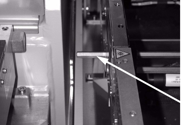
: Check whether the hexagonal shafts are set for the maximum conveyor width. The hexagonal
shaft should connect to the conveyor tray at the outer movable conveyor side wall.
2
2
2
2
2
2
2
2
2
2
2
2
Hexagonal shafts