3OM-1286-007_w.pdf - 第240页
6-7 AJQEDT -ID [8] [6] [7] [9] Fig. 3F3-3 "Device Offset" T ab Sheet (3) [10] Fig. 3F3-4 "Device Offset" T ab Sheet (4) 0606-005 2.1 Device Offset Data
6-6
AJQEDT-ID
0606-005
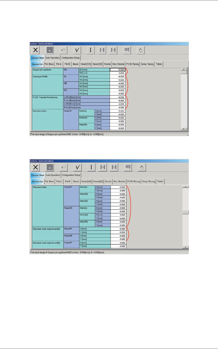
2.1.1 Device Offset
When the "Device Ofst" tab is pressed in the "Device Offset" tab sheet, the
following tab sheet appears.
[1]
[2]
[3]
Fig. 3F3-1 "Device Offset" Tab Sheet (1)
[4]
[5]
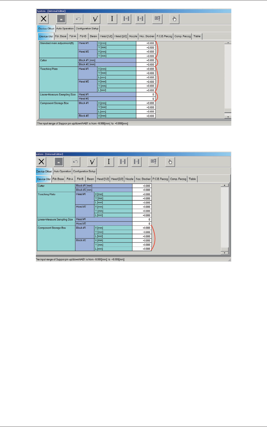
Fig. 3F3-2 "Device Offset" Tab Sheet (2)
2.1 Device Offset Data
6-7
AJQEDT-ID
[8]
[6]
[7]
[9]
Fig. 3F3-3 "Device Offset" Tab Sheet (3)
[10]
Fig. 3F3-4 "Device Offset" Tab Sheet (4)
0606-005
2.1 Device Offset Data
6-8
AJQEDT-ID
[1] Support pin up/down
NA
B1 and B2 [mm]
This is the offset data for the origin position of the support pin up/down
axis which ascends or descends during PCB positioning.
A plu
s (+) value decreases the ascending stroke during PCB positioning.
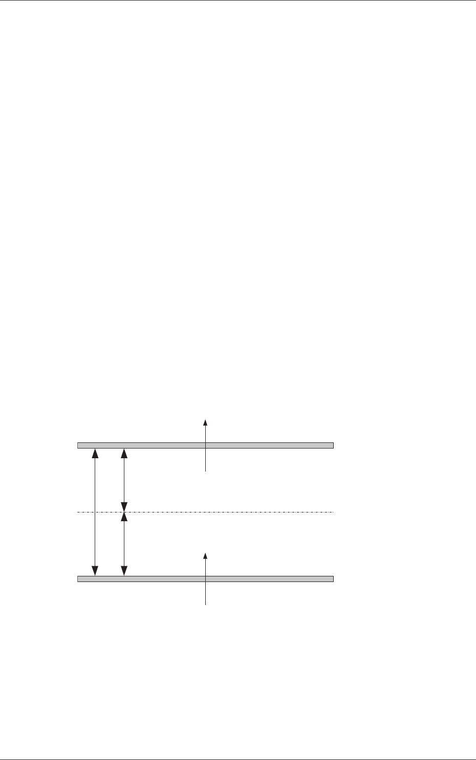
[2] Conveyor Width
NL, NB and NR
W1 and W2 [mm]
This offset is used to adjust the conveyor width to the absolute values.
When the conveyor width is set up to the specified one based on
the positioning center, a difference will be caused in the dimension
between the actually measured value (the distance between the machine
p
ositi
oning center and each chute) and the half of the specified width. In
this case, enter the difference in each text box.
W1 Offset :
A plus value must be entered when the actually
measured width is narrower than the half of the
specified one.
W2 Offset :
A minus value must be entered when the actually
measured width is narrower than the half of the
specified one.
A
A/2
A/2
NL-W1
NR-W1
NB-W1
NL-W2
NR-W2
NB-W2
(+)
(-)
(+)
(-)
Fig. 3F6
0606-005
2.1 Device Offset Data