3OM-1286-007_w.pdf - 第260页
6-27 AJQEDT -ID 2.1.10 NL Origin Of fset When the "Head [1/2]" tab is pressed in the "Device Offset" tab sheet and the "NL Origin Ofst" tab is selected, the following tab sheet appears. Fig.…
6-26
AJQEDT-ID
0606-005
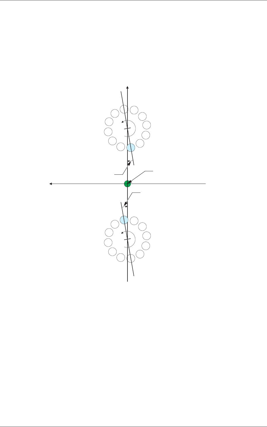
Head 1 and Head 2
Z [deg]
The set parameters are used to adjust the angular deviations of the line
connecting Nozzles 1 and 7 at the head rotational Z-phase position
based on the machine coordinate reference.
When the line is tilted clockwise in the machine reference X/Y
coordinate system, a plus sign must be affixed to the offset data.
Xm (+)
Ym (+)
Xm-Ym : Machine Reference
Coordinate System
1
2
3
4
5
6
7
8
9
10
11
12
1
2
3
4
5
6
7
8
9
10
11
12
DD Motor Z-Phase
Stop Position
DD Motor Z-Phase
Stop Position
DD (+)
DD (+)
Head Rotational Angle Offset
Head Rotational Angle Offset
Pm. Machine Reference
Coordinate Origin
Fig. 3F22
2.1 Device Offset Data
6-27
AJQEDT-ID
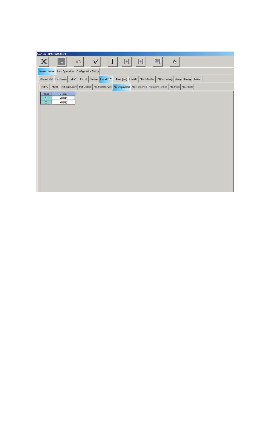
2.1.10 NL Origin Offset
When the "Head [1/2]" tab is pressed in the "Device Offset" tab sheet and the
"NL Origin Ofst" tab is selected, the following tab sheet appears.
Fig. 3F26 "NL Origin Ofst" Tab Sheet
Head 1 and Head 2
L (Height) [mm]
The
set parameters are used to correct the deviations between the nozzle
U/D mechanism and the nozzle roller caused while the NL axis is
rotating.
0606-005
2.1 Device Offset Data
6-28
AJQEDT-ID
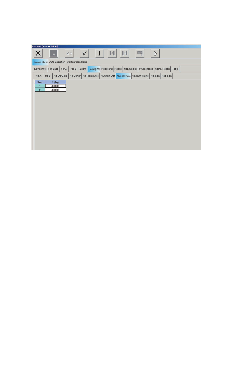
2.1.11 Nozzle Selection Axis Offset
When the "Head [1/2]" tab is pressed in the "Device Offset" tab sheet and the
"Noz. Sel Axis" tab is selected, the following tab sheet appears.
Fig. 3F27 "Noz. Sel Axis" Tab Sheet
Head 1 and Head 2
Z (Angle) [deg]
The se
t parameters are used to adjust the angular deviations between the
head rotational and nozzle selection axes.
0606-005
2.1 Device Offset Data