3OM-1286-007_w.pdf - 第274页
6-41 AJQEDT -ID [1] X (Horizontal) and Y (V ertical) [mm] This offset data is used to adjust the positional deviations compared with the design dimensions of the nozzle stocker unit positions (viewed from the PCB positio…
6-40
AJQEDT-ID
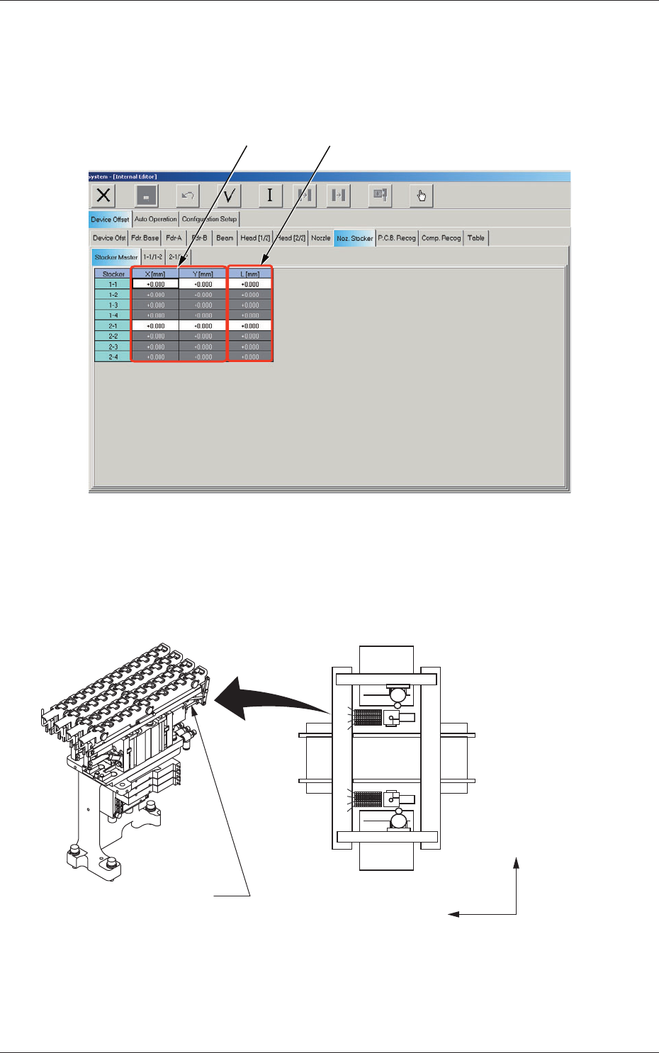
2.1.20 Stocker Master Offset
When the "Noz. Stocker" tab is pressed in the "Device Offset" tab sheet and
the "Stocker Master" tab is selected, the following tab sheet appears.
[1]
[2]
Fig. 3F31 "Stocker Master" Tab Sheet
Stockers
1-1 through1-4, and 2-1 through 2-4,
1-4
1-3
1-2
1-1
2-1
2-2
2-3
2-4
4
3
2
1
1
2
3
4
5
6
7
8
9
10
11
12
Placement Reference
X/Y Coordinate System
Y(+)
X(+)
2
(Front Side of Machine)
(Rear Side of Machine)
Nozzle Stocker A
1
Fig. 3F31-1
2.1 Device Offset Data
0606-005
6-41
AJQEDT-ID
[1] X (Horizontal) and Y (Vertical) [mm]
This offset data is used to adjust the positional deviations compared
with the design dimensions of the nozzle stocker unit positions (viewed
from the PCB positioning X/Y coordinates (Machine Reference X/Y
Coordinates: Origin P0)). The value base on the machine reference XL
coordinate system must be entered in each text box.
[2]
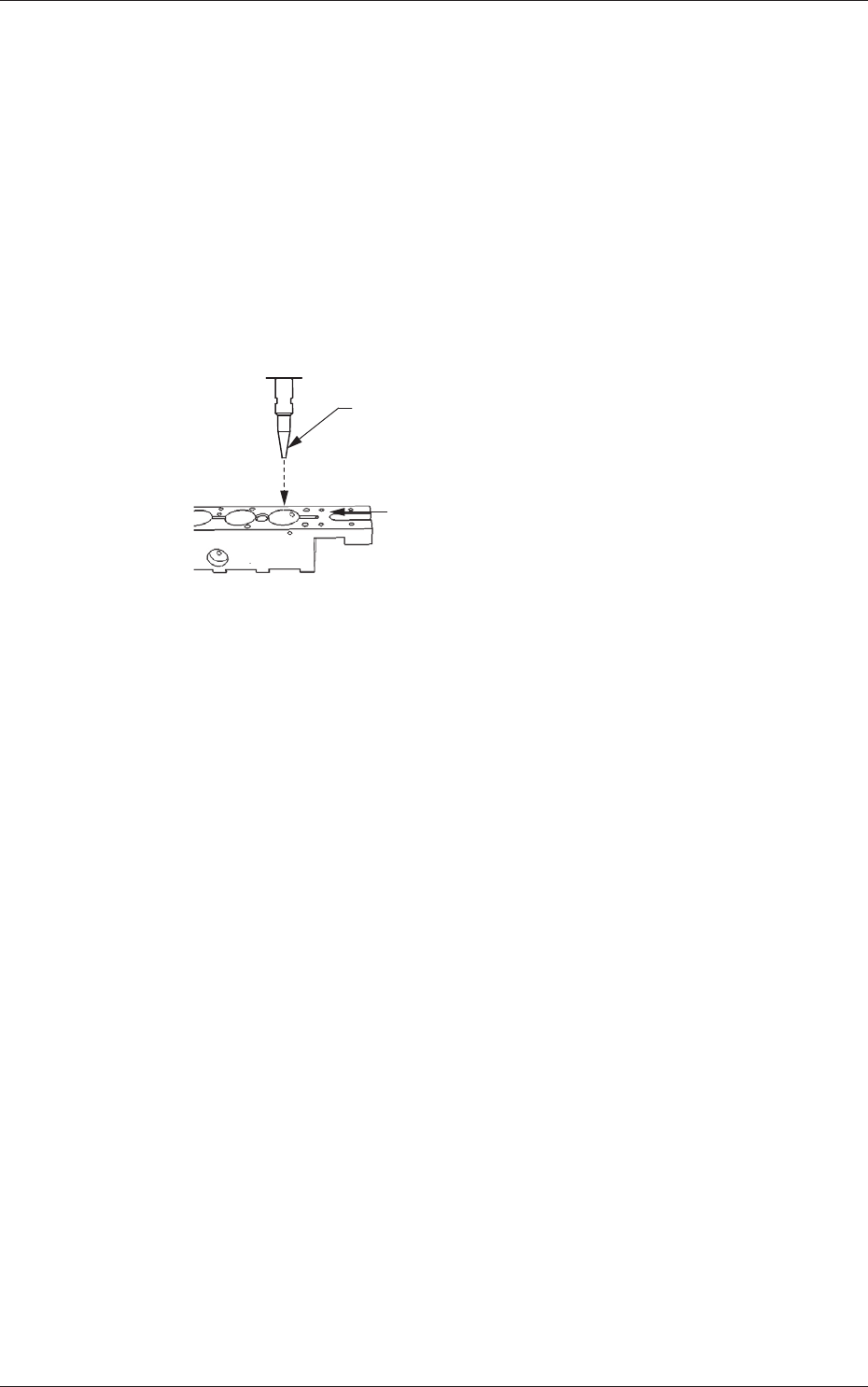
L (Height) [mm]
When a value is entered with a plus (+) sign, the nozzle change
position (height) is changed in the L (+) direction, concluding that the
descending stroke has increased.
L(+)
Nozzle
Nozzle Mounting Level
(Upper Surface of Nozzle Stocker Block)
Fig. 3F32
0606-005
2.1 Device Offset Data
6-42
AJQEDT-ID
0606-005
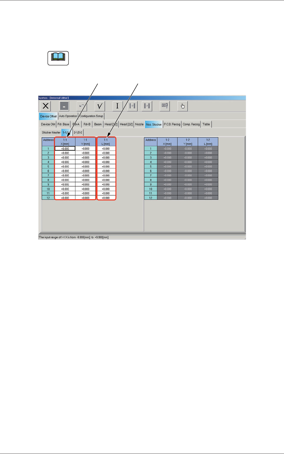
2.1.21 Nozzle Stocker Offset
When the "Noz. Stocker" tab is pressed in the "Device Offset" tab sheet and
the "1-1/1-2" tab is selected, the following tab sheet appears.
Note
As for the "2-1/2-2" tab sheet, the same contents as the "1-1/1-2" tab sheet
are displayed.
[1] [2]
Fig. 3F33 Nozzle Stocker "1-1/1-2" Tab Sheet
2.1 Device Offset Data