3OM-1286-007_w.pdf - 第287页
6-54 AJQEDT -ID [1] Auto feeder axis adjustment set Set the sensitivity parameters which follow up the data learned by using the statistical method in the feeder (B) offset data. New Feeder (B) Offset = Old Feeder (B) Of…
6-53
AJQEDT-ID
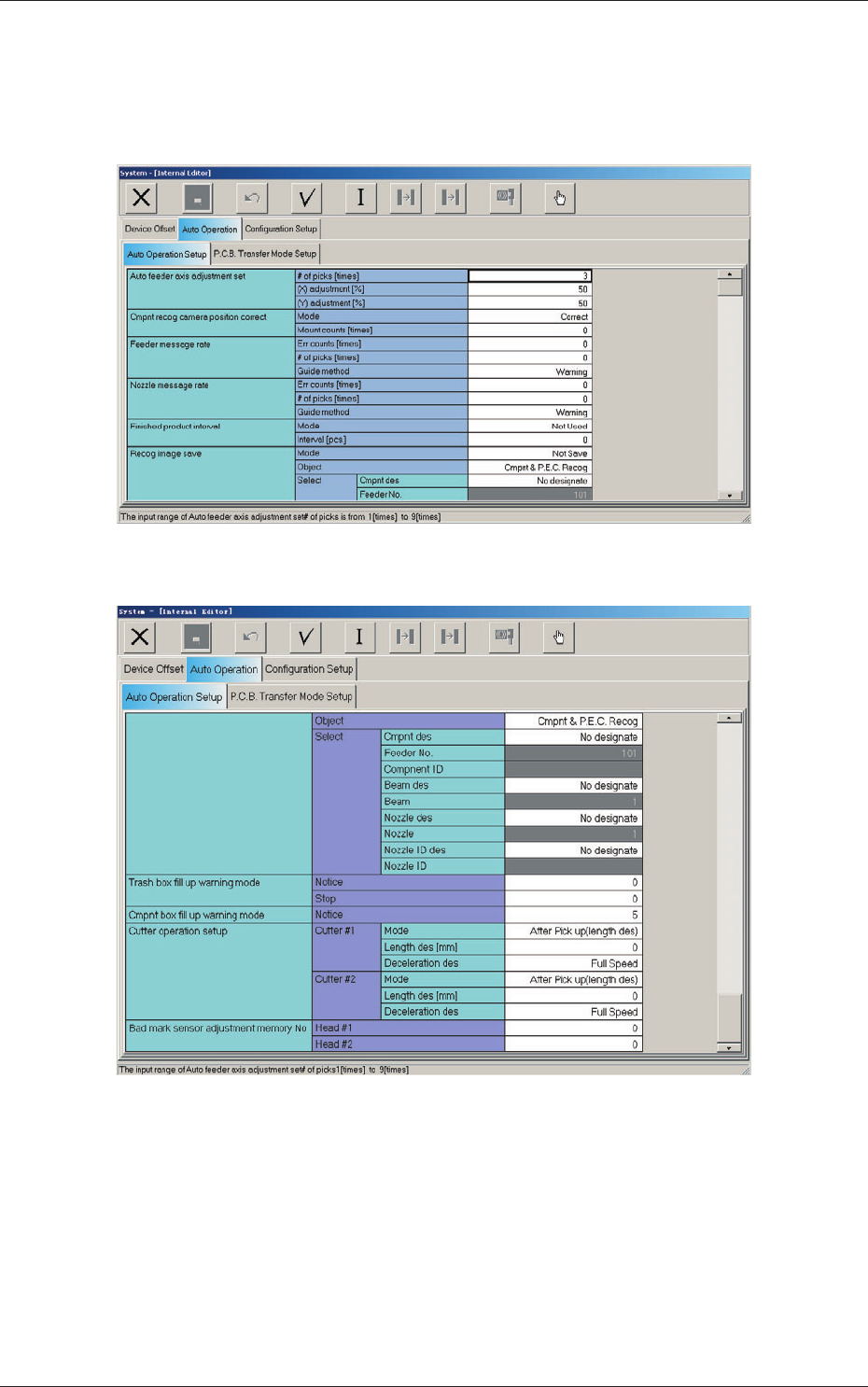
2.2.1 Auto Operation Setup
When the "Auto Operation Setup" tab is pressed in the "Auto Operation" tab
sheet, the following tab sheet appears.
Fig. 3F43-1 "Auto Operation Setup" Tab Sheet (1)
Fig. 3F43-2 "Auto Operation Setup" Tab Sheet (2)
2.2 Auto Operation
0606-005

6-54
AJQEDT-ID
[1] Auto feeder axis adjustment set
Set the sensitivity parameters which follow up the data learned by using
the statistical method in the feeder (B) offset data.
New Feeder (B) Offset
=
Old Feeder (B) Offset +
(Mean V
alue of "n" T
imes (Deviation))
×
Coefficient ((X) adjustment or (Y)
adjustment)
# of picks [times]
Set the total number of collected samples when data is updated or
changed.
(X) adjustment [%]
Select one of the following options as a feedback coefficient of the
mean of the X-direction deviation.
10, 20, 30, 40, 50, 60, 70, 80, 90, Full
(Y) adjustment [%]
Select one of the following options as a feedback coefficient of the
mean of the
Y-direction deviation.
10, 20, 30, 40, 50, 60, 70, 80, 90, Full
[2] Cmpnt recog camera position correct
Mode
"Correct" or "No Correct" can be selected to determine whether or
not the component recognition camera position should be corrected
periodically
.
Note
It is recommended to set "Correct" in normal cases.
Mount counts [times]
Press the icon (
) to open the "Ten-Key Pad" window and enter
either "0" or "1 to 9999".
0 :
No automatic correction operation is performed for
each number of components to be placed.
1 to 9999
:
Corre
ct
ion is made according to the specified number
of components to be placed.
0606-005
2.2 Auto Operation
6-55
AJQEDT-ID
Note
(a) When "Correct" is set in the "Mode" text box, the corrective actions
take place automatically before the PCB is transferred to the PCB
positioning section and the component recognition operation is
performed.
(b) When the number of components (components to be placed on
a production PCB) per beam is smaller than the set number of
components, the corrective actions do not take place in the middle of
placement operation.
Because the internal counter for interval monitoring is cleared
through the above-described corrective actions (the actions which
take place during PCB positioning), no corrective actions take place
in compliance with the number of components to be placed on several
PCBs.
[3] Feeder message rate
Err counts, # of picks [times]
Set the parameters to show the feeder slot No. (Fdr. No.) of the tape
feeder whose pickup rate has deteriorated during automatic operation.
When the number of picks has reached the specified value, the
parameter in the "Error counts" text box is cleared.
Note
The number of picks and pick-up errors is managed for each individual
feeders but the parameters of "Error counts" and "# of picks" is equally
reflected on every feeder.
Guide method
"Warning", "Stop (Cycle stop), or "Pause" can be selected to determine
in which mode the machine should be set when the number of pickup
errors has reached the specified error counts before the number of picks
reaches the specified number of picks. When "Warning" is selected, a
warning message is issued as machine information. "Stop (Cycle stop)"
stops the machine after one cycle of operation and "Pause" sets the
machine in the "P
AUSE" mode.
Note
When both "Error counts" and "# of picks" are set "0" (zero) or "Error
counts" is set to a number larger than "# of picks", no warning message is
issued.
0606-005
2.2 Auto Operation