00197443-02_IM_707_1_DE_EN - 第51页
Station S oftware 70 7.1 / Ins tallation Man ual Ausgabe 05/2014 E dition 51 7.9 Necessary C alibrat ion S teps After upgra ding fr om station s oftware 70 x a nd first bo oting of the station sof tware, som e calibrati …
Station Software 707.1 / Installation Manual Ausgabe 05/2014 Edition
50
7.5 SX4 Placement Machine
► When the SX4 placement machine is booted for the first time you have to select the SX4
Flexible entry for Machine frame manually in the Auto-configuration, if there are tables in
outer position in processing area 2, as this is not detected automatically via sensors.
Tables in outer position are used when stationary cameras are in use.
► Otherwise you select the SX4 High Speed entry.
7.6 DX-Series Placement Machines
► When the DX placement machines are booted for the first time you have to select the following
options manually:
– For C&P12 placement head: height position (altitude)
– Lamp indicators (two-colored or three-colored)
– Table position:
inner 60 tracks
outer 60 tracks
outer with 30 tracks + free location for tray or WPC
– Confirm/reject 3-D Coplan sensor
7.7 Checking/Updating the Embedded Software
If the correct eSW versions are not available on the machine, the machine boot gets interrupted.
► In this case, perform an eSW download.
► Start an overall reference run for the machine.
7.8 Storage Location of the Machine Files (Calibration Data etc.)
The machine-specific configuration, measurement and parameter data is stored in XML files under
C:\Sirio\Work\Individual. These XML files contain all the calibration data.
Station Software 707.1 / Installation Manual Ausgabe 05/2014 Edition
51
7.9 Necessary Calibration Steps
After upgrading from station software 70x and first booting of the station software, some calibration
steps are required.
Requirements:
– The eSW versions have been updated.
– The reference run has been sucessfully performed.
– A calibration nozzle (1235) has to be available on every C&P20A placement head at
segment 1.
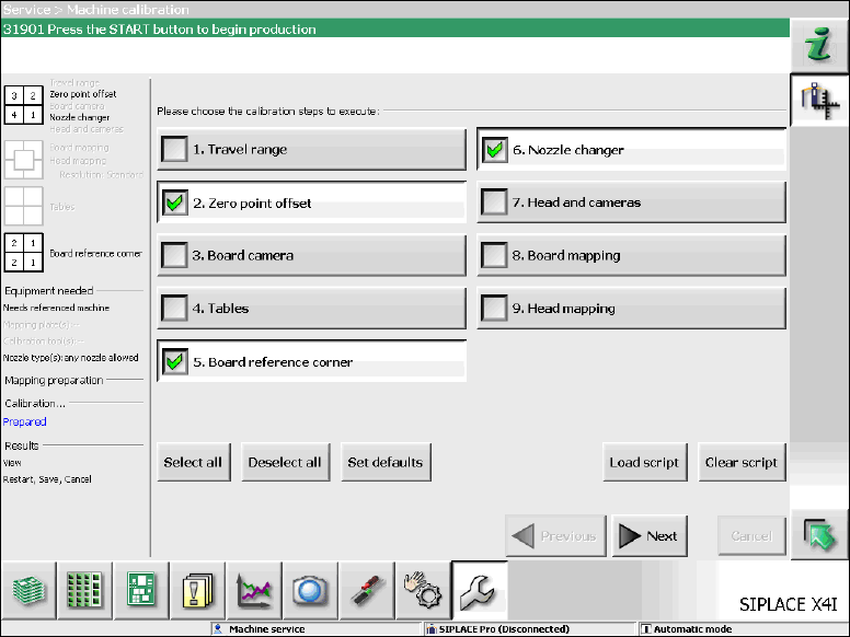
Figure 7-10: Required calibration steps
► Select the calibration steps that are highlighted in the figure and click on Next.
► Select all possible components in the following input masks (all conveyor lanes, all gantries, all
nozzle changers).
Station Software 707.1 / Installation Manual Ausgabe 05/2014 Edition
52
7.10 Storing Calibration Data in the EEPROM
In order to use the fast head exchange feature, the head specific calibration data has to be stored
in the EEPROM after upgrading from station software 70x. For placement heads with no head
specific calibration data stored within the EEPROM, the available data on the station computer will
be stored in the EEPROM of the respective placement head as follows.
Requirement:
The eSW versions have been updated.
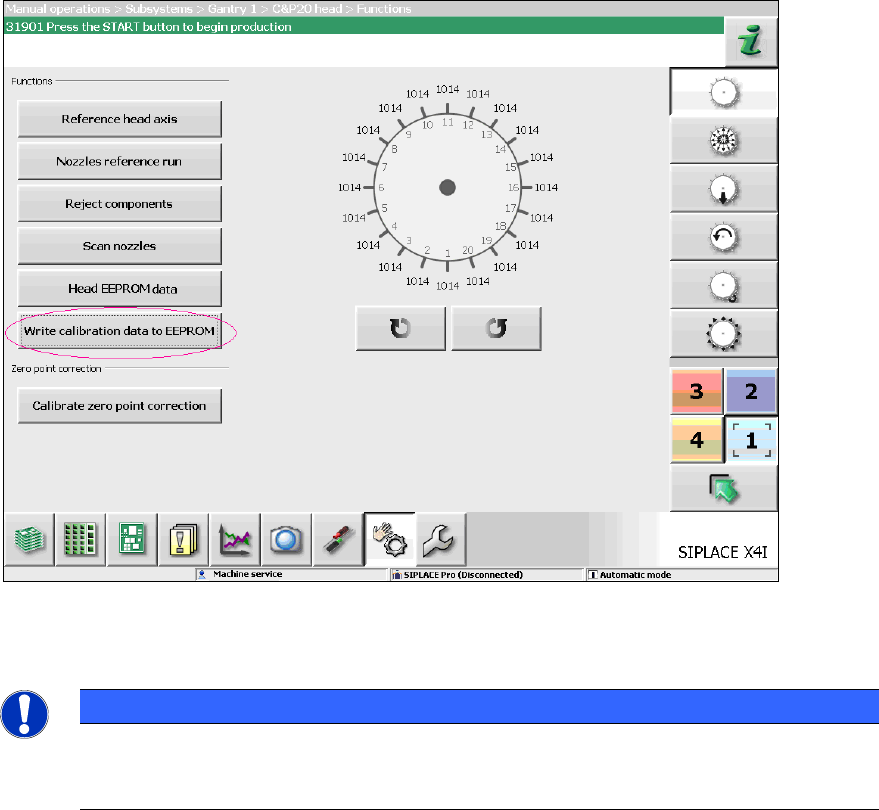
Figure 7-11: Storing calibration data in the EEPROM
► Perform the highlighted function for each placement head.
NOTICE
After the storing calibration data step, the message 37200 Changed heads
detected should disappear. Otherwise you will have to reboot the machine. If the
message still is displayed after rebooting, please inform the SIPLACE Service.