TR7600 SIII_Hardware_en_v_2_0_4 - 第10页
Test Research, Inc . iv TR7600 SIII Seri es User Gu ide – Hardw are T ables Table 1: Operating & Storage Environment for TR7600 SIII ....... .... ....... .... ...... ..... ..... ...... 2 Table 2: Stat us Indicator Li…

Test Research, Inc.
TR7600 SIII Series User Guide – Hardware iii
Figure 40: Right Gate Speed Control ............................................................................. 49
Figure 41: Pulling and Pushing Control .......................................................................... 50
Figure 42: Rear and Front Conveyor .............................................................................. 50
Figure 43: Front Conveyor Control ................................................................................. 51
Figure 44: Rear Conveyor Control .................................................................................. 51
Figure 45: Sensor Arrangement for Left-In Board .......................................................... 52
Figure 46: Sensors for Left-In Board .............................................................................. 52
Figure 47: Sensor Arrangement for Right-In Board ........................................................ 53
Figure 48: Sensors for Right-In Board ............................................................................ 53
Figure 49: Digital Fiber Sensor/Initialization ................................................................... 54
Figure 50: Digital Fiber Sensor/Default Settings ............................................................ 54
Figure 51: Digital Fiber Sensor/ [Super] mode ............................................................... 55
Figure 52: Digital Fiber Sensor/ [D_on] mode ................................................................ 55

Test Research, Inc.
iv TR7600 SIII Series User Guide – Hardware
Tables
Table 1: Operating & Storage Environment for TR7600 SIII ............................................ 2
Table 2: Status Indicator Light Description ..................................................................... 21
Table 3: Error Codes Of Movement along X and U Axes .............................................. 38
Table 4: Error Codes of Movement along Y, Z, V and W Axes ...................................... 45
Test Research, Inc.
TR7600 SIII Series User Guide – Hardware 1
1 I
NTRODUCTION
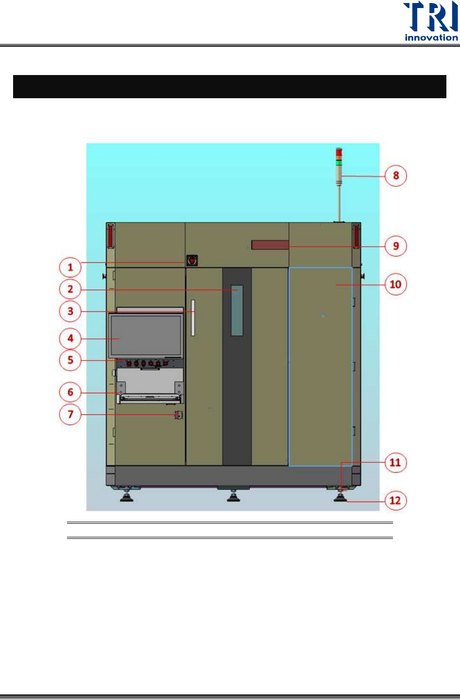
The figure below shows the machine front view and Human-Machine Interface (HMI or HCI)
located in the top-right corner.
Figure 1: Front View
1) Emergency Stop 6) Keyboard
11) Adjustable Screw Of
Floor Stand
2) Lead Glass Window 7) Power Switch 12) Floor Stand
3) Front Door Handle 8) Signal Tower
4) Monitor 9) X-Ray Warning LED Light
5) Control Panel 10) Front Right Cover