TR7600 SIII_Hardware_en_v_2_0_4 - 第12页
Test Research, Inc . 2 TR7600 SIII Seri es User Gu ide – Ha rdware The Operating and St orage environmental parameters are listed in t he following table. Operating Storage A mb ient Te mperature: 0-40°C (32-10 4°F) -40-…
Test Research, Inc.
TR7600 SIII Series User Guide – Hardware 1
1 I
NTRODUCTION
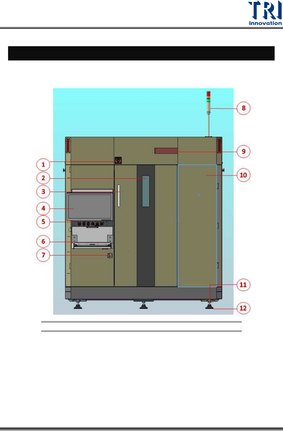
The figure below shows the machine front view and Human-Machine Interface (HMI or HCI)
located in the top-right corner.
Figure 1: Front View
1) Emergency Stop 6) Keyboard
11) Adjustable Screw Of
Floor Stand
2) Lead Glass Window 7) Power Switch 12) Floor Stand
3) Front Door Handle 8) Signal Tower
4) Monitor 9) X-Ray Warning LED Light
5) Control Panel 10) Front Right Cover

Test Research, Inc.
2 TR7600 SIII Series User Guide – Hardware
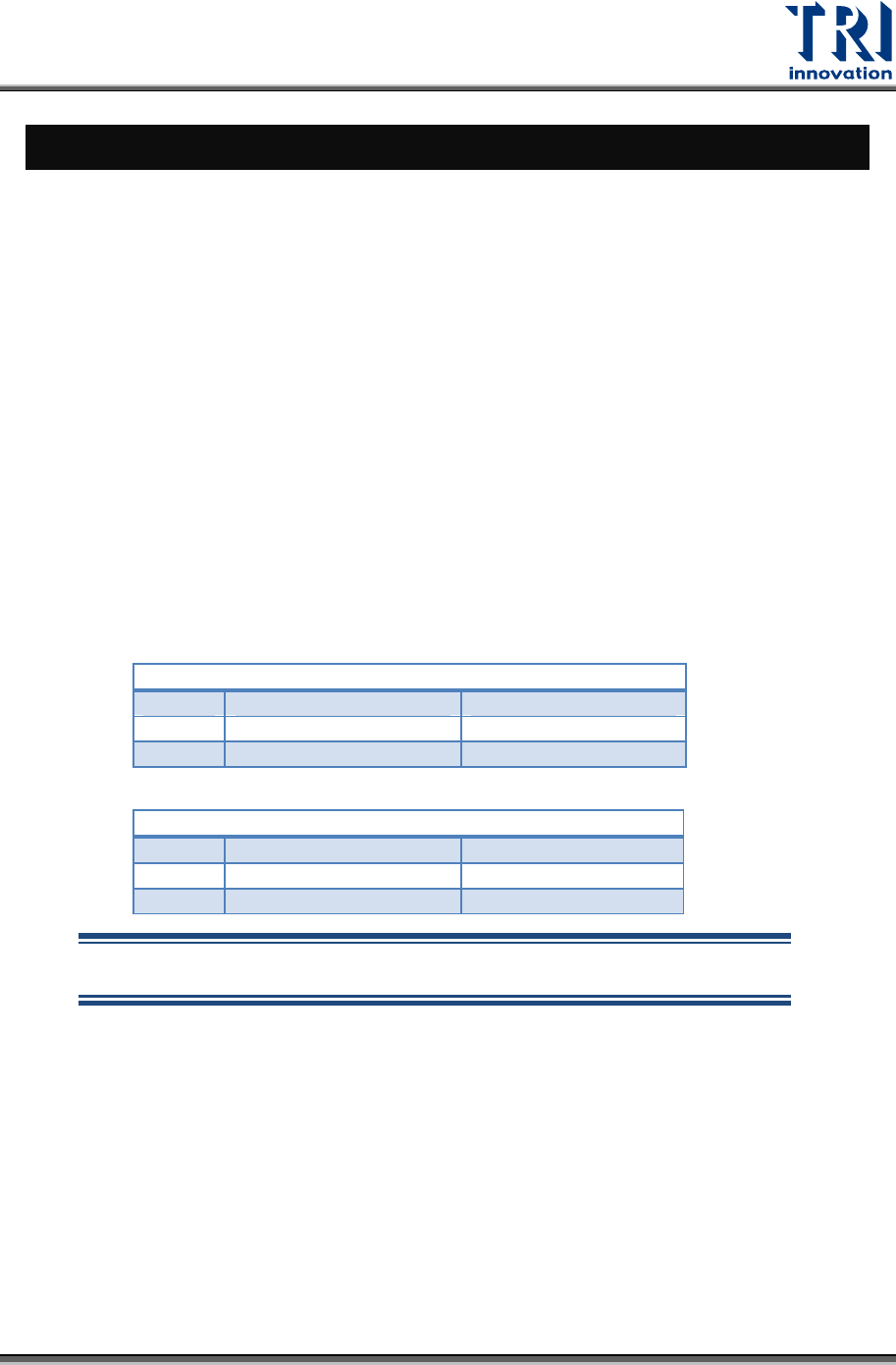
The Operating and Storage environmental parameters are listed in the following table.
Operating Storage
Ambient Temperature:
0-40°C (32-104°F) -40-66°C (-40-151°F)
Max. Temperature Gradient:
10°C/hour (18°F/hour) 10°C/hour (18°F/hour)
Relative Humidity:
20-80% non-condensing Up to 95% non-condensing
Max. Humidity Gradient:
10%/hour 10%/hour
Max. Wet Bulb Temperature:
25°C (77°F) 46°C (115°F)
Max. Dew Point Temperature:
2°C (36°F) 2°C (36°F)
The power requirement for the TR7600 SIII is AC 200-240V/20A, three-phase, 50/60 Hz.
Table 1: Operating & Storage Environment for TR7600 SIII
Test Research, Inc.
TR7600 SIII Series User Guide – Hardware 3
2 HMI
&
PLC
2.1 Architecture and Function
The Human-Machine Interface (HMI) is mainly used to set the testing modes.
The Programmable Logic Controller (PLC) is mainly used to control the PCB I/O Board
Holder as well as exchange sampling or Pass/Fail signals (through the RS-232 cable);
usually when the machine is set to In-Line mode there will be a greater chance of I/O board
issues or loader/unloader error. The possible errors and solutions are introduced below.
1) If the PCBs to be tested are relatively long, when the testing is completed and the PCB
is unloaded and the next PCB loaded, the PCBs may cover Sensor1 (Loader Sensor)
and Sensor2 (Brake Sensor) at the same time. The current program logic of the PLC
requires that Sensor1 and Sensor2 must not both be triggered at the same time, or the
alarm buzzer will activate and the new board will automatically be unloaded. In such a
situation the relative positions of Sensor1 and Sensor2 should be adjusted to avoid
being simultaneously triggered and leading to abnormal operation. The exception is
when equipment is set for simultaneous In and Out.
2) Loader/Unloader Connection: Please install wiring according to SMEMA specifications.
PORT1
–
UP LINE
Y104
Black (1) / Green (2)
Ready
X
2
A
Red (3) / Blue (4)
Board Available
X
2
B
Yellow (5) / White (6)
Spare
PORT2
–
DOWN LINE
X98
Black (1) / Green (2)
Ready
Y106
Red (3) / Blue (4)
Board Available
Y105
Yellow (5) / White (6)
OK: Short; NG: Open
NOTE: The above connections are all single point relays so there are no
positive or negative polarity differences.