TR7600 SIII_Hardware_en_v_2_0_4 - 第26页
Test Research, Inc . 16 TR7600 SIII Series Us er Guide – Ha rdware Continuous T est Continuous T est: If both [T EST] m ode and [C ontinuous Tes t] are enabled, no m atter what the software comm and is, the system will…

Test Research, Inc.
TR7600 SIII Series User Guide – Hardware 15
Others
No Air Test: When there is no air supply, you can click [Yes] to simulate testing.
Open Door Test: When this function is enabled, the mechanism can move normally, but
the X-ray will not be turned on if the front or rear door is open. This function is usually
used for testing or maintenance.
One Door Open: If this function is enabled and system is set to [Left-In-Left-Out] or [Right
-In-Right-Out], the gate on the side which is not used will not move.
No Hold: Click [Yes] to make the conveyor release the board.
Go to 2nd Stage: After you enable 2-stage function, enable [Go to 2nd Stage] function for
second project to scan the images.
Enable 2 Stage: Open the 2-stage function.
PLC Version
Machine Settings: Choose which machine type and port to connect the PLC.
Panel Language: Choose Chinese or English to display.
Speed Settings
High Speed: This is the normal I/O speed. The speed range has the upper limit of
5000PPS and the lower limit of 100PPS.
Low Speed: This is the slow down speed. The speed range has the upper limit of
1000PPS and the lower limit of 20PPS.
Bypass Speed: This is the bypass speed. The speed range has the upper limit of
3200PPS and the lower limit of 100PPS.
Barcode Settings
2DBarCode: Click [Yes] if 2D Barcode is used.
Skip Barcode: Click [Yes] and then the machine won t wait for barcode and inspects
boards straightforward.
ReadBarCodeAfterBoardIn: Click [Yes] if the pre-scanning barcode function is enabled.
Trigger By Port: Click [Yes] to enable the barcode reader to read the barcode before the
board enters the gate.
Test Research, Inc.
16 TR7600 SIII Series User Guide – Hardware
Continuous Test
Continuous Test: If both [TEST] mode and [Continuous Test] are enabled, no matter
what the software command is, the system will control the panel and undergo the
below process repeatedly: board-lockedboard-releasedboard-outboard-in.
Test Count: Input test times and click [Set] to finish the setup.
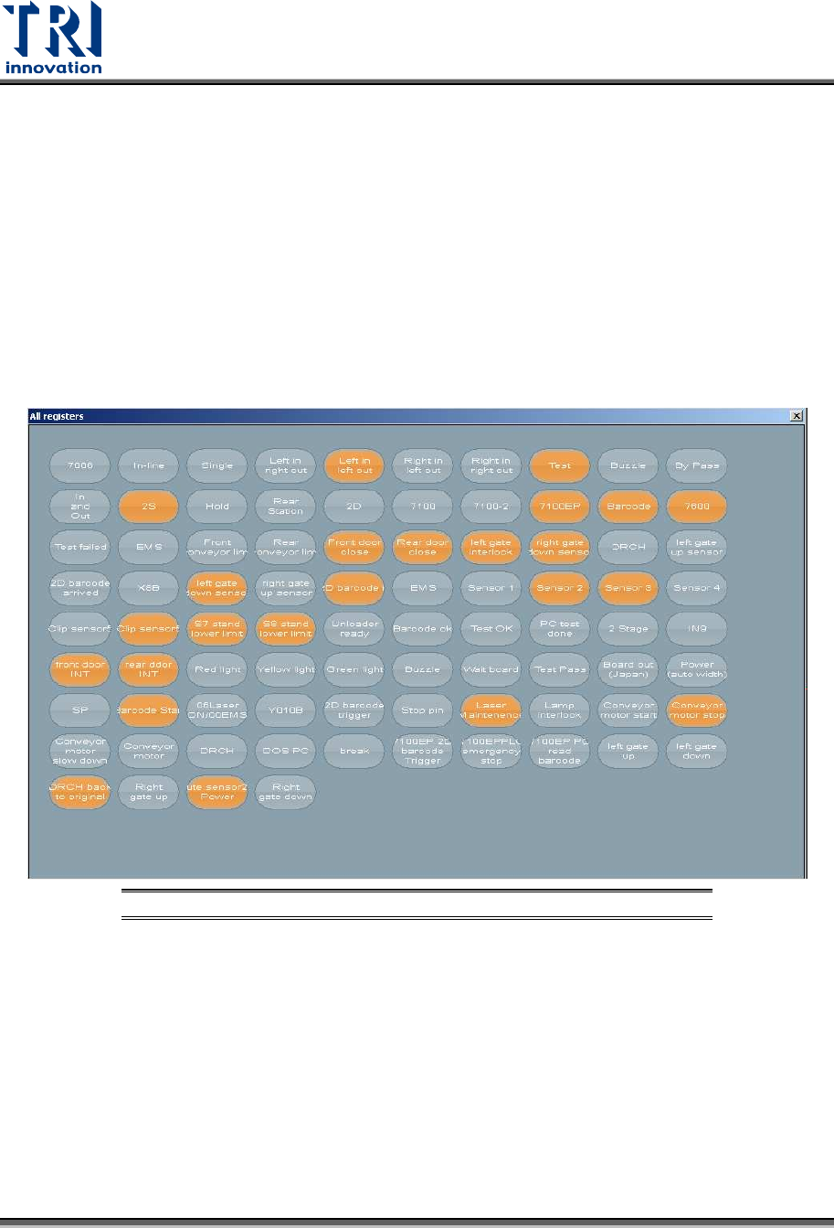
3.6 Surveillance
You can ignore this section, since only professional TRI engineers will use below
functions.
Figure 17: VPLC/ Surveillance
Test Research, Inc.
TR7600 SIII Series User Guide – Hardware 17
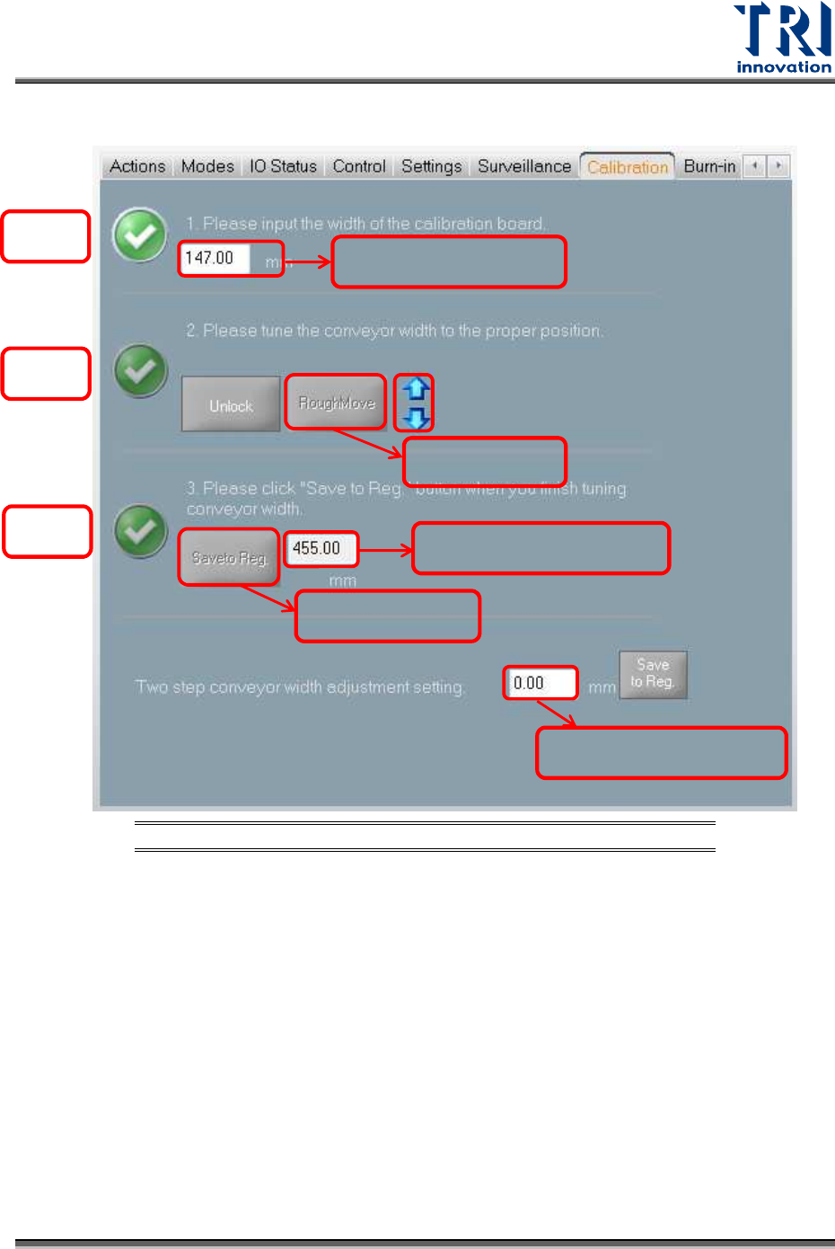
3.7 Calibration
Figure 18: VPLC/Calibration
Width: Input the width of the calibration board.
Unlock: Click to release the clipped board.
Move to Rough: Click to move the conveyor to the calibration board width that is input by
you. After you click the [Move to Rough] button, the machine will move the conveyor to
the origin point first and then move to the calibration board width later.
Save to Registry: After you click [Save to Registry], the machine will calculate the
maximum conveyor width and save the current parameters to the registry file. The
maximum conveyor width after calibration should be the same as the default maximum
conveyor width.
Two stage overlapped width: Input the overlap width of 2 Stage function and then click
[Save to Reg.] button to update the setup to the registry.
Tick 1
Tick 3
Tick 2
Calibration board width
Move to Rough
width
Save to registry
width
Maximum conveyor width
2-stage overlapped width