TR7600 SIII_Hardware_en_v_2_0_4 - 第27页
Test Research, Inc . TR7600 SIII Seri es User Gu ide – Hardw are 17 3.7 Calibrat ion Figure 18: VPLC/Calibrati on W idt h: Input t he width of the calibration board. Unlock: Click to release the clipped board. M ov…
Test Research, Inc.
16 TR7600 SIII Series User Guide – Hardware
Continuous Test
Continuous Test: If both [TEST] mode and [Continuous Test] are enabled, no matter
what the software command is, the system will control the panel and undergo the
below process repeatedly: board-lockedboard-releasedboard-outboard-in.
Test Count: Input test times and click [Set] to finish the setup.
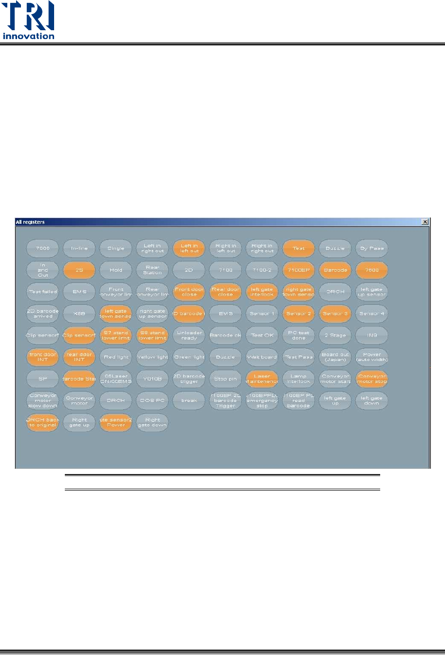
3.6 Surveillance
You can ignore this section, since only professional TRI engineers will use below
functions.
Figure 17: VPLC/ Surveillance
Test Research, Inc.
TR7600 SIII Series User Guide – Hardware 17
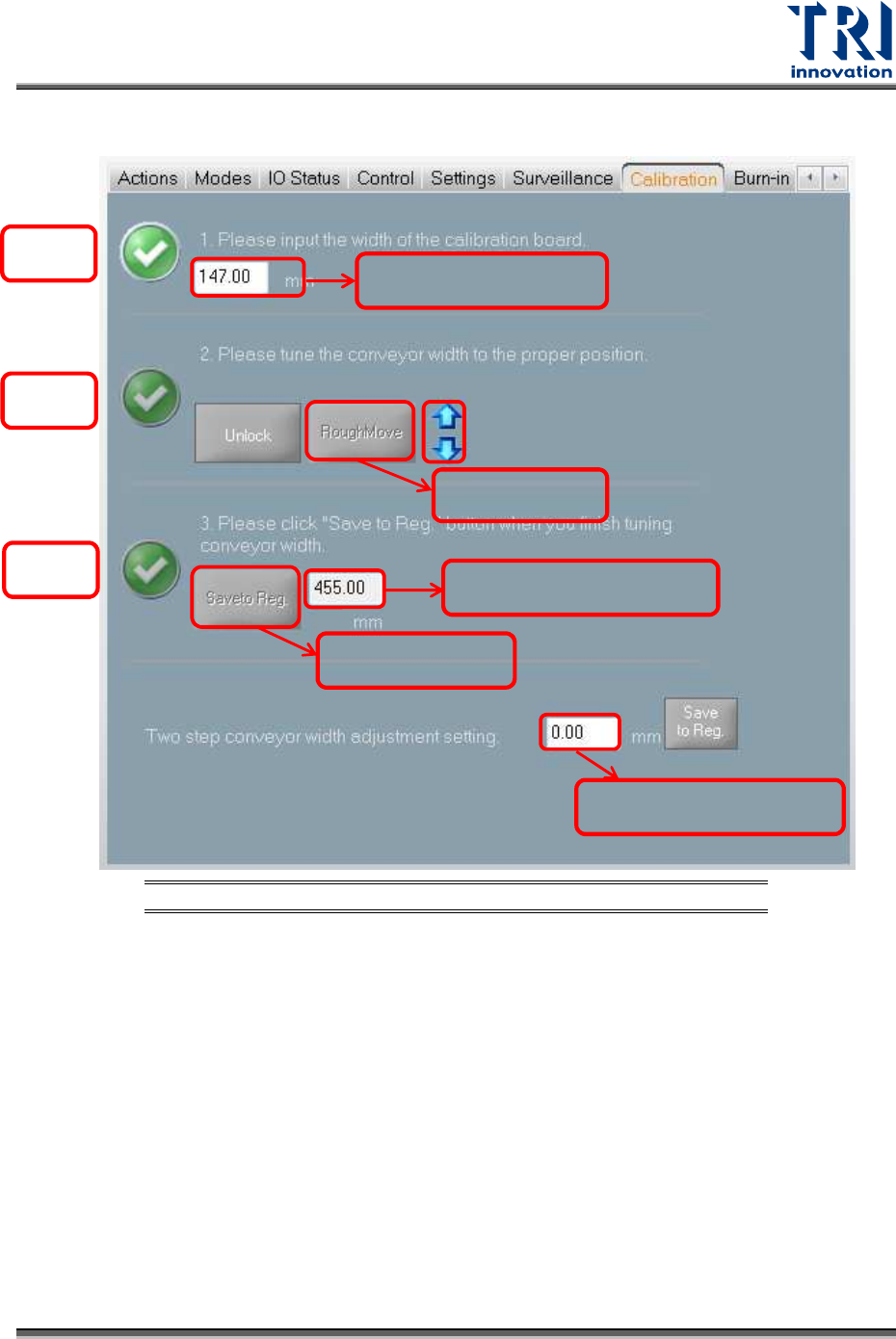
3.7 Calibration
Figure 18: VPLC/Calibration
Width: Input the width of the calibration board.
Unlock: Click to release the clipped board.
Move to Rough: Click to move the conveyor to the calibration board width that is input by
you. After you click the [Move to Rough] button, the machine will move the conveyor to
the origin point first and then move to the calibration board width later.
Save to Registry: After you click [Save to Registry], the machine will calculate the
maximum conveyor width and save the current parameters to the registry file. The
maximum conveyor width after calibration should be the same as the default maximum
conveyor width.
Two stage overlapped width: Input the overlap width of 2 Stage function and then click
[Save to Reg.] button to update the setup to the registry.
Tick 1
Tick 3
Tick 2
Calibration board width
Move to Rough
width
Save to registry
width
Maximum conveyor width
2-stage overlapped width

Test Research, Inc.
18 TR7600 SIII Series User Guide – Hardware
If you want to re-calibrate the conveyor width, please follow the steps below:
1) Measure the calibration board width.
2) Input the calibration board width in the [Board Width] field.
3) Click [Tick 2] and [Move to Rough] in sequence. The conveyor will move to the
position assigned by you approximately.
4) Measure the conveyor width.
5) Change the fine-tune distance to meet your needs in the [Fin-Tune Distance] field and
then use the [Up Arrow] and [Down Arrow] buttons to fine-tune the conveyor width to
the precise assigned position.
6) Put the calibration board into the machine and slide it on the conveyor to double
confirm the width setup is correct.
7) Click [Tick 3] and [Save to Registry] in sequence to save changes to the registry. The
machine will display the maximum conveyor width based on your calibration. The
maximum conveyor width after calibration should be the same as the default
maximum conveyor width.