TR7600 SIII_Hardware_en_v_2_0_4 - 第31页
Test Research, Inc. TR7600 SIII Series User Gu ide – Hardwa re 21 4 HARDWARE OVERVIEW 4.1 Towe r Status Indicator Lights Tower Status Indicator Lights are located on the top of the machine. Figure 21: Tower Status Indica…
Test Research, Inc.
20 TR7600 SIII Series User Guide – Hardware
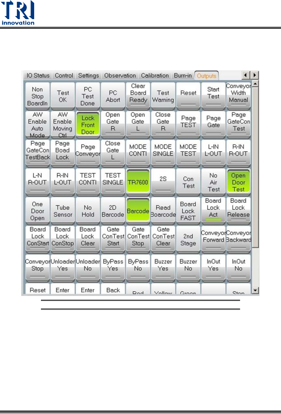
3.9 Output
Users can ignore this section, since only professional TRI engineers will use below
functions.
Figure 20: VPLC – Warning – CONV. WIDTH MOTOR ABNORMAL
Test Research, Inc.
TR7600 SIII Series User Guide – Hardware 21
4 HARDWARE
OVERVIEW
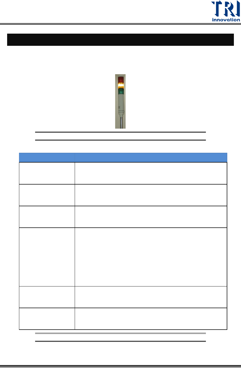
4.1 Tower Status Indicator Lights
Tower Status Indicator Lights are located on the top of the machine.
Figure 21: Tower Status Indicator Lights
LIGHTS DESCRIPTION
Red Light
1) When users finish the setup and the machine is ready to test,
the red light is on.
2) When users click the Reset button, the red light is on.
Flashing Red Light 1) When users press the Emergency button, the red light is
flashing.
Yellow Light 1) When users enable Bypass function, the yellow light is
on.
Flashing Yellow
Light
1) When the reset process is finished, the yellow light
flashes.
2) When the machine asks for the board, the yellow light
flashes.
3) When the machine finishes the inspection, the yellow
light flashes.
Green Light 1) When the machine scans the board, the green light is
on.
Flashing Green
Light
1) When the machine is importing the board, the green light
flashes.
Table 2: Status Indicator Light Description
Test Research, Inc.
22 TR7600 SIII Series User Guide – Hardware
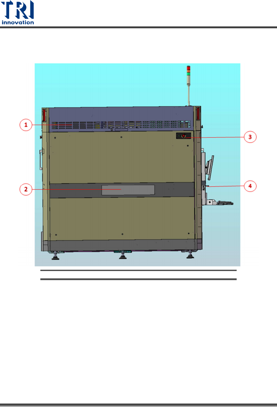
4.2 Module Board Layout
4.2.1 L
EFT
S
IDE
V
IEW OF THE
S
YSTEM
Figure 22: Left Side View of the System
1) Left Module Board Box
2) Left Gate
3) Emergency Stop
4) Adjustable Computer Table Lock