TR7600 SIII_Hardware_en_v_2_0_4 - 第32页
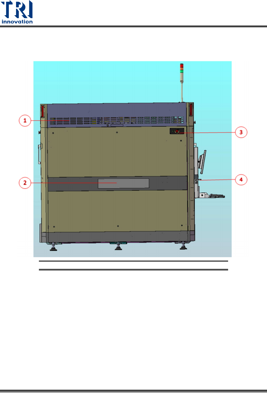
Test Research, Inc . 22 TR7600 SIII Series Us er Guide – Ha rdware 4.2 Modul e Board La yout 4.2.1 L EFT S IDE V IEW OF THE S YSTEM Figure 22: Left Side Vi ew of th e System 1) Left Module Board Box 2) Left Gate 3) Emerg…
Test Research, Inc.
TR7600 SIII Series User Guide – Hardware 21
4 HARDWARE
OVERVIEW
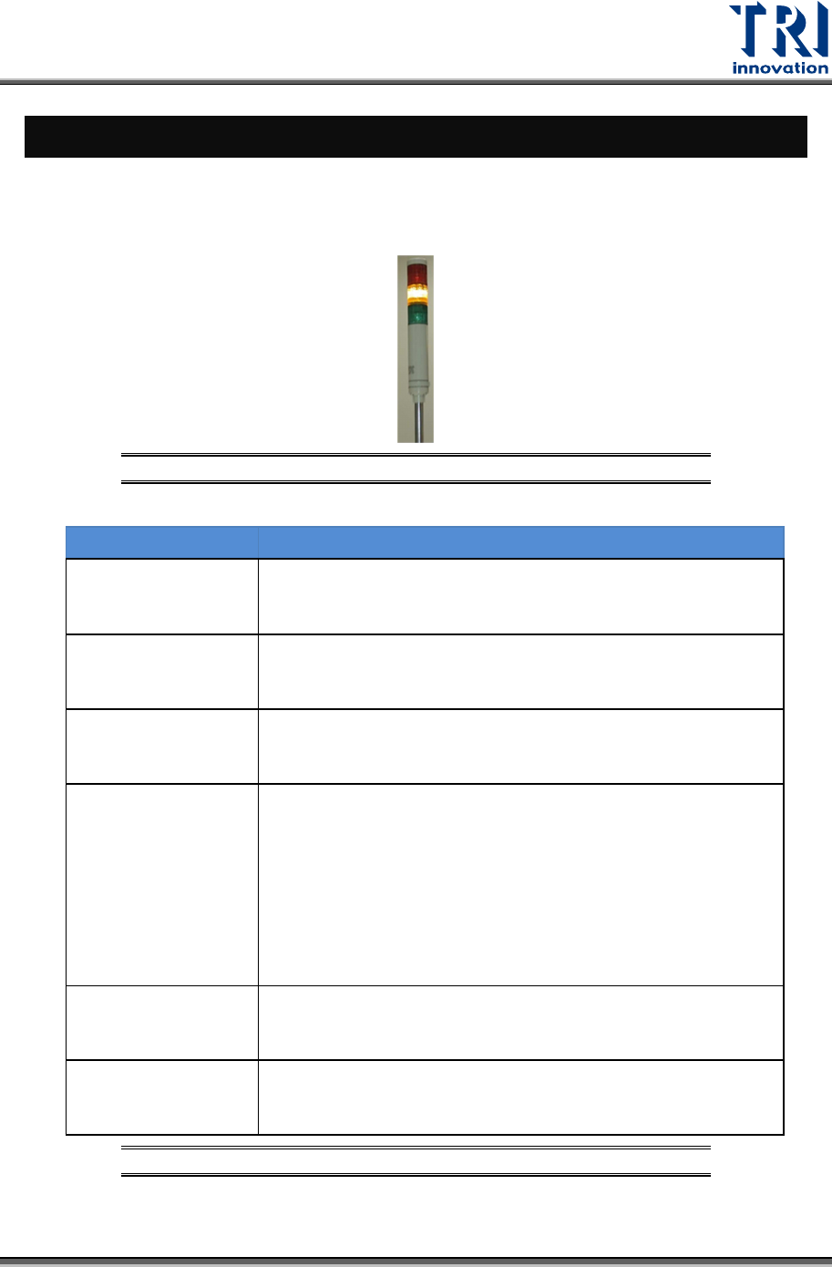
4.1 Tower Status Indicator Lights
Tower Status Indicator Lights are located on the top of the machine.
Figure 21: Tower Status Indicator Lights
LIGHTS DESCRIPTION
Red Light
1) When users finish the setup and the machine is ready to test,
the red light is on.
2) When users click the Reset button, the red light is on.
Flashing Red Light 1) When users press the Emergency button, the red light is
flashing.
Yellow Light 1) When users enable Bypass function, the yellow light is
on.
Flashing Yellow
Light
1) When the reset process is finished, the yellow light
flashes.
2) When the machine asks for the board, the yellow light
flashes.
3) When the machine finishes the inspection, the yellow
light flashes.
Green Light 1) When the machine scans the board, the green light is
on.
Flashing Green
Light
1) When the machine is importing the board, the green light
flashes.
Table 2: Status Indicator Light Description
Test Research, Inc.
22 TR7600 SIII Series User Guide – Hardware
4.2 Module Board Layout
4.2.1 L
EFT
S
IDE
V
IEW OF THE
S
YSTEM
Figure 22: Left Side View of the System
1) Left Module Board Box
2) Left Gate
3) Emergency Stop
4) Adjustable Computer Table Lock
Test Research, Inc.
TR7600 SIII Series User Guide – Hardware 23
4.2.2 L
EFT
M
ODULE
B
OARD
L
AYOUT
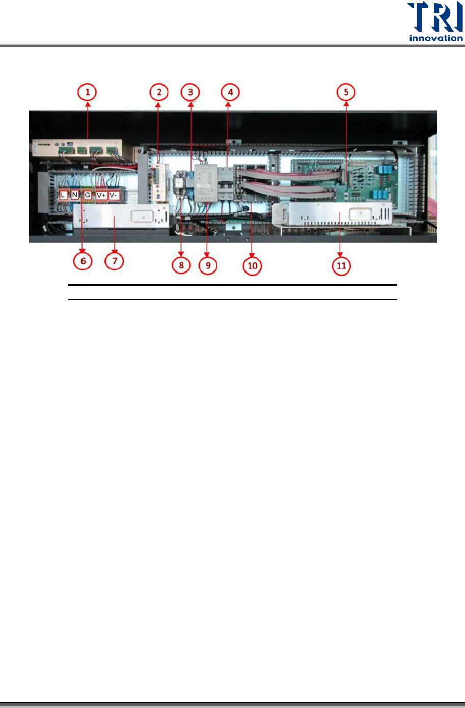
Figure 23: Left Module Board Layout
1) Conveyor Driver
2) Auto Width Driver
3) X-Ray Power Relay
4) Extension Cable NFB
5) Module Board
6) AC&DC Bus
7) X-Ray Power Supply
8) Camera Power Relay
9) System Power Supply
10) PLC
11) Camera Power Supply