TR7600 SIII_Hardware_en_v_2_0_4 - 第34页
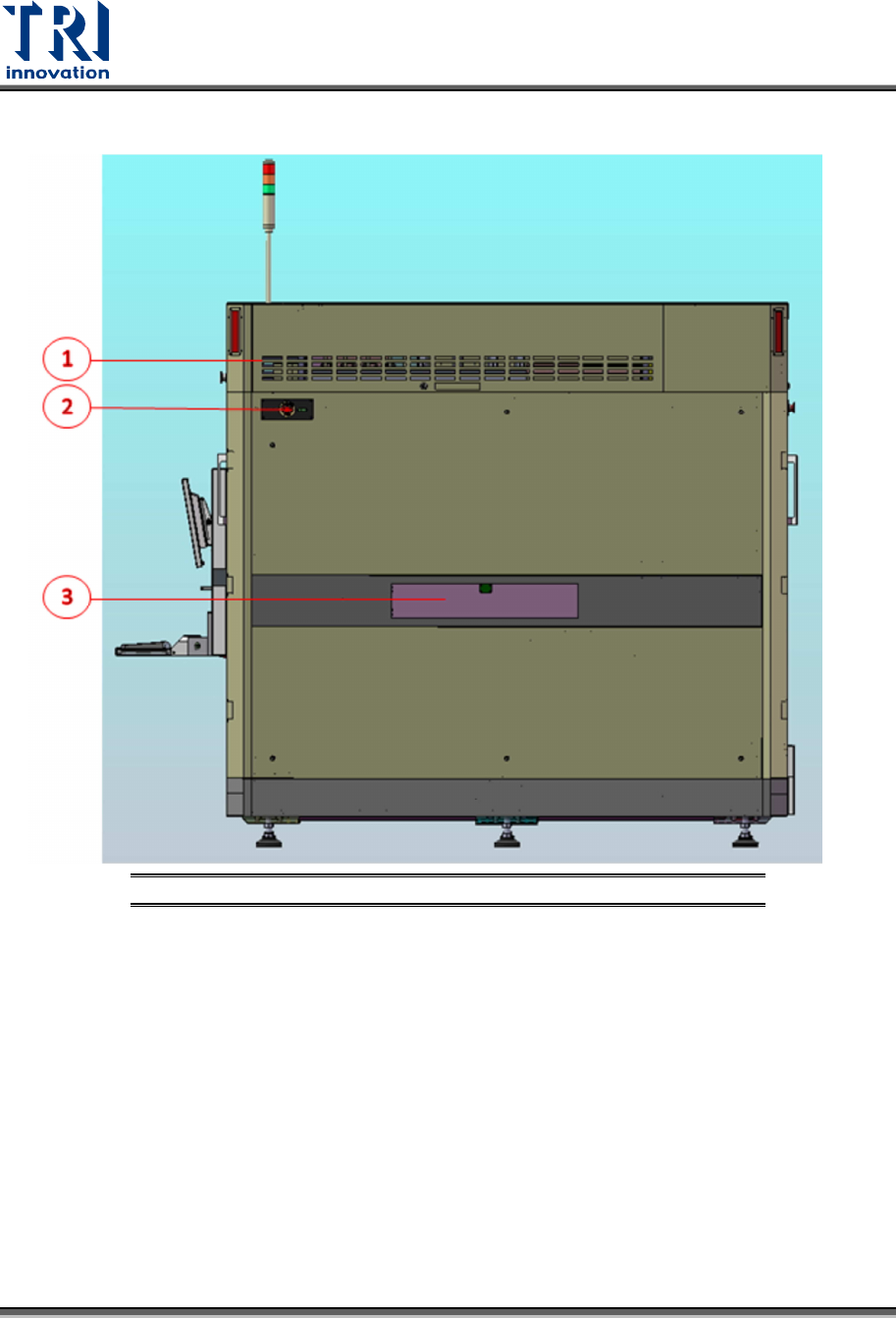
Test Research, Inc . 24 TR7600 SIII Series Us er Guide – Ha rdware 4.2.3 R IGHT S IDE V IEW OF THE S YSTEM Figure 24: Right Side Vie w of the System 1) Right Modu le Board Box 2) Emergency Stop 3) Right Gate
Test Research, Inc.
TR7600 SIII Series User Guide – Hardware 23
4.2.2 L
EFT
M
ODULE
B
OARD
L
AYOUT
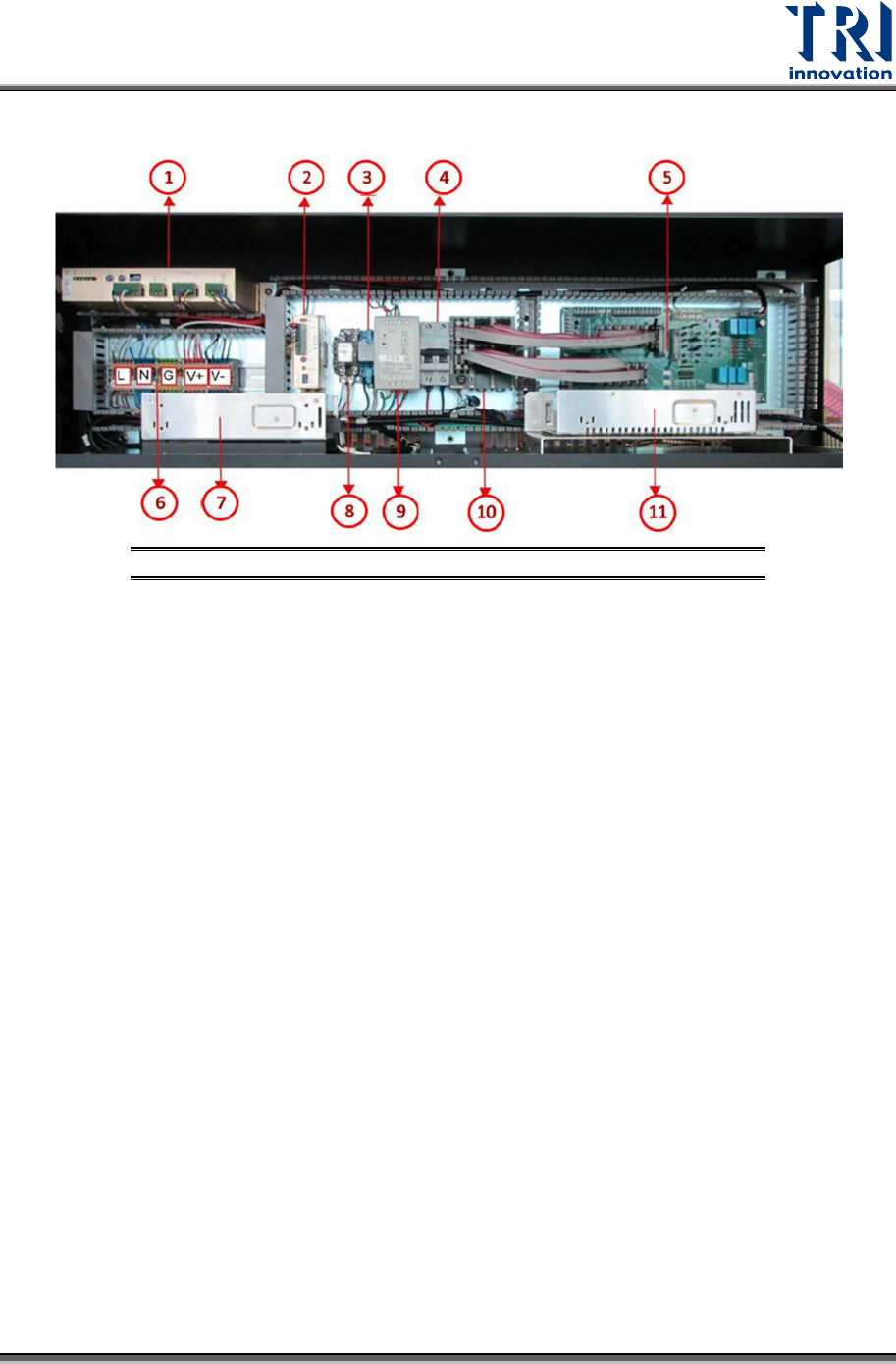
Figure 23: Left Module Board Layout
1) Conveyor Driver
2) Auto Width Driver
3) X-Ray Power Relay
4) Extension Cable NFB
5) Module Board
6) AC&DC Bus
7) X-Ray Power Supply
8) Camera Power Relay
9) System Power Supply
10) PLC
11) Camera Power Supply
Test Research, Inc.
24 TR7600 SIII Series User Guide – Hardware
4.2.3 R
IGHT
S
IDE
V
IEW OF THE
S
YSTEM
Figure 24: Right Side View of the System
1) Right Module Board Box
2) Emergency Stop
3) Right Gate
Test Research, Inc.
TR7600 SIII Series User Guide – Hardware 25
4.2.4 R
IGHT
M
ODULE
B
OARD
L
AYOUT
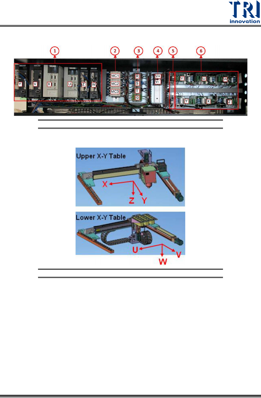
Figure 25: Right Module Board Layout
Figure 26: Six Motion Axes
1) Servo Motor Driver
2) Magnetic Contactor
3) AC Bus
4) DC Bus
5) Servo Motor Break Relay
6) DSP Slave Module