TR7600 SIII_Hardware_en_v_2_0_4 - 第35页
Test Research, Inc. TR7600 SIII Series User Gu ide – Hardwa re 25 4.2.4 R IGHT M ODULE B OARD L AYOUT Figure 25: Right Module Board Layout Figure 26: Six Motion Axes 1) Servo Moto r Driv er 2) Ma gnetic C ontactor 3) AC …
Test Research, Inc.
24 TR7600 SIII Series User Guide – Hardware
4.2.3 R
IGHT
S
IDE
V
IEW OF THE
S
YSTEM
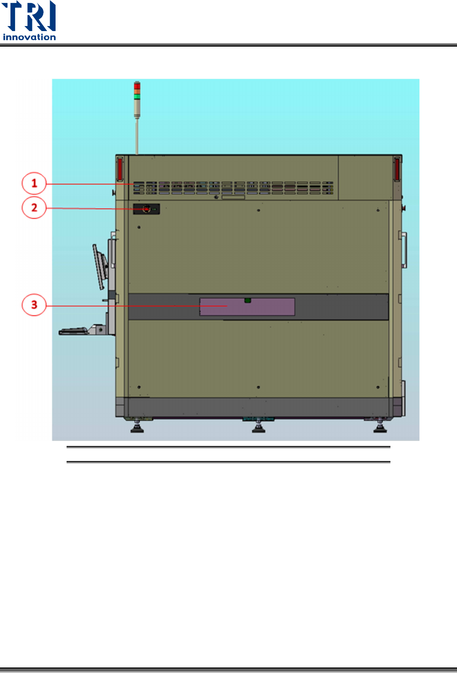
Figure 24: Right Side View of the System
1) Right Module Board Box
2) Emergency Stop
3) Right Gate
Test Research, Inc.
TR7600 SIII Series User Guide – Hardware 25
4.2.4 R
IGHT
M
ODULE
B
OARD
L
AYOUT
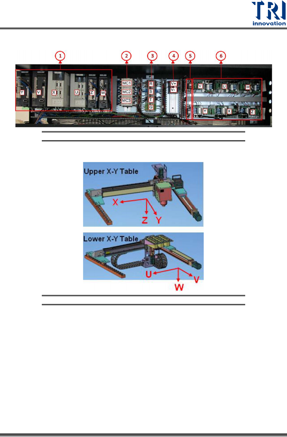
Figure 25: Right Module Board Layout
Figure 26: Six Motion Axes
1) Servo Motor Driver
2) Magnetic Contactor
3) AC Bus
4) DC Bus
5) Servo Motor Break Relay
6) DSP Slave Module
Test Research, Inc.
26 TR7600 SIII Series User Guide – Hardware
4.2.5 R
EAR
V
IEW OF THE
S
YSTEM
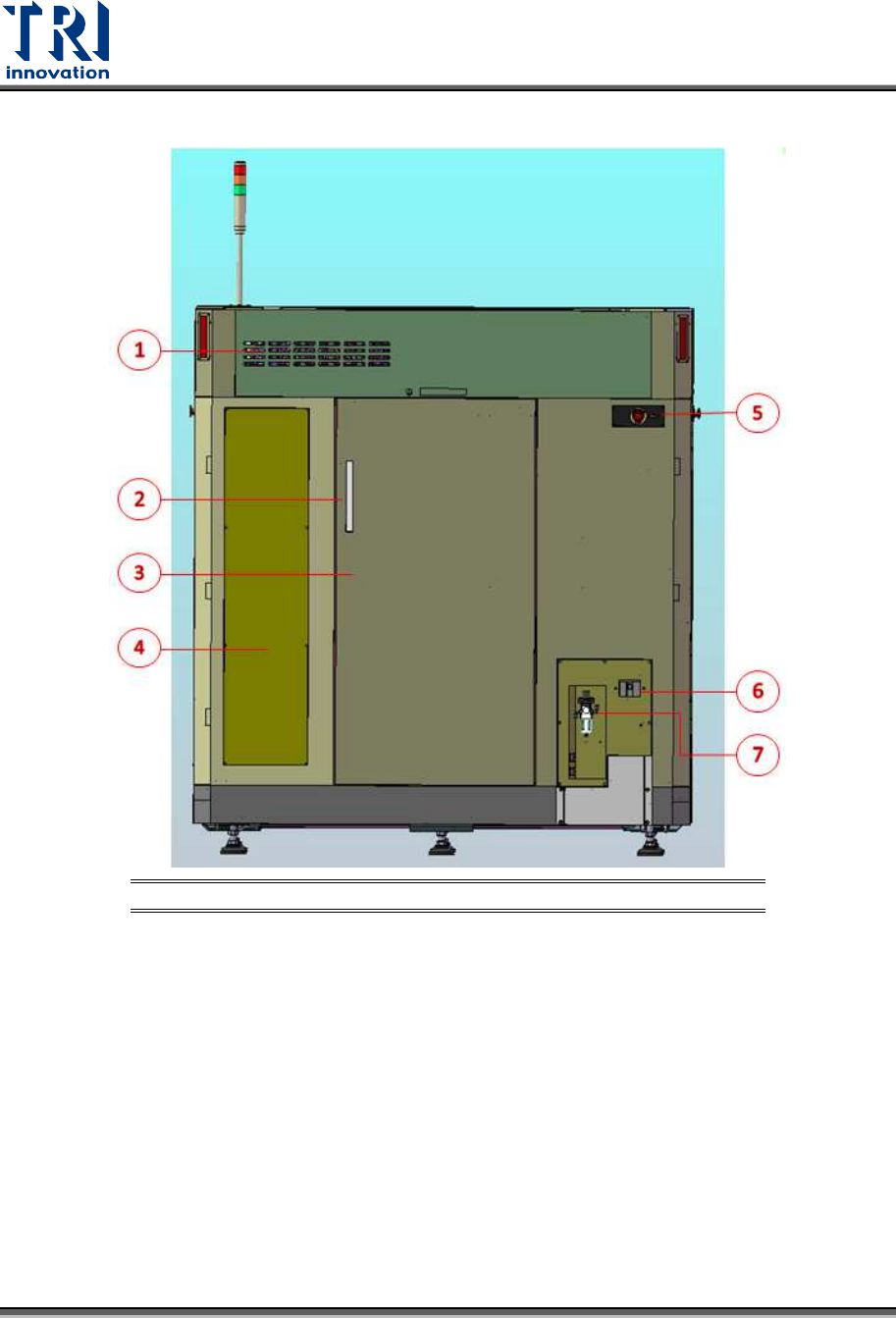
Figure 27: Rear View of the System
1) Upper Module Box Door
2) Back Door Handle
3) Back Door
4) Back Left Cover
5) Emergency Stop
6) Power Socket
7) Air Pressure Control Box