TR7600 SIII_Hardware_en_v_2_0_4 - 第40页
Test Research, Inc . 30 TR7600 SIII Series Us er Guide – Ha rdware 5 O PTICAL M ODULE The m achine’s optical module consists of an X-Ray T ube and C ameras. Their positions are shown in the following pictures. Figure 31:…
Test Research, Inc.
TR7600 SIII Series User Guide – Hardware 29
4.2.8 R
EAR
–I
NTERIOR
P
OWER
B
OARD
L
AYOUT
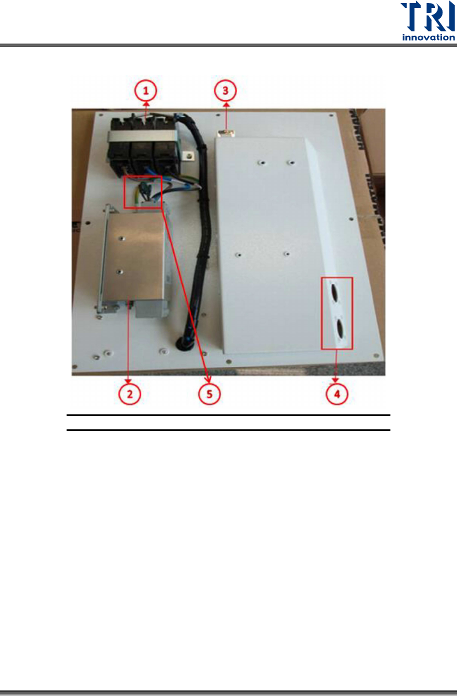
Figure 30: Power Board Layout
1) Main NFB
2) EMI Filter
3) Network Cable Socket
4) SMEMA (Port 1 for Loader and Port 2 for Unloader)
5) Surge Absorbers
Test Research, Inc.
30 TR7600 SIII Series User Guide – Hardware
5 O
PTICAL
M
ODULE
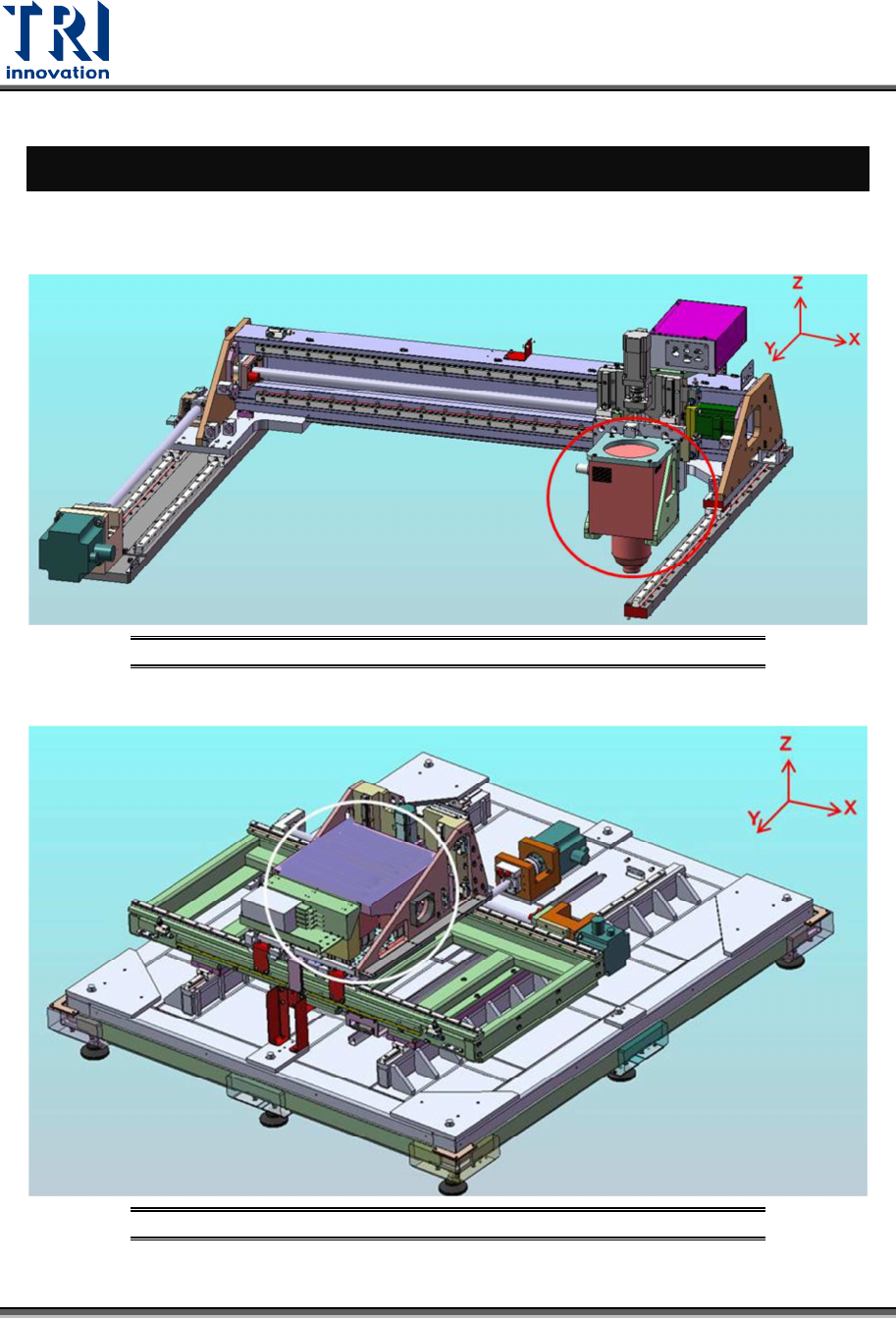
The machine’s optical module consists of an X-Ray Tube and Cameras. Their positions are
shown in the following pictures.
Figure 31: Optical Module/X-Ray Tube
Figure 32: Optical Module/Cameras
Test Research, Inc.
TR7600 SIII Series User Guide – Hardware 31
6 T
ROUBLESHOOTING
6.1 Movement along X and U Axes Error
The hardware error from the movement along X and U axes is indicated on the motor driver
LED display as shown below. Press the Mode button to toggle the display if necessary. In
case of any hardware error, see the Alarm code in the reference table below for
troubleshooting.
If no error code is shown on the LED display, but the movement along X and U axes is still
not functioning properly, please contact TRI FAE for further assistance.
6.1.1 C
HECK THE
MR-J2
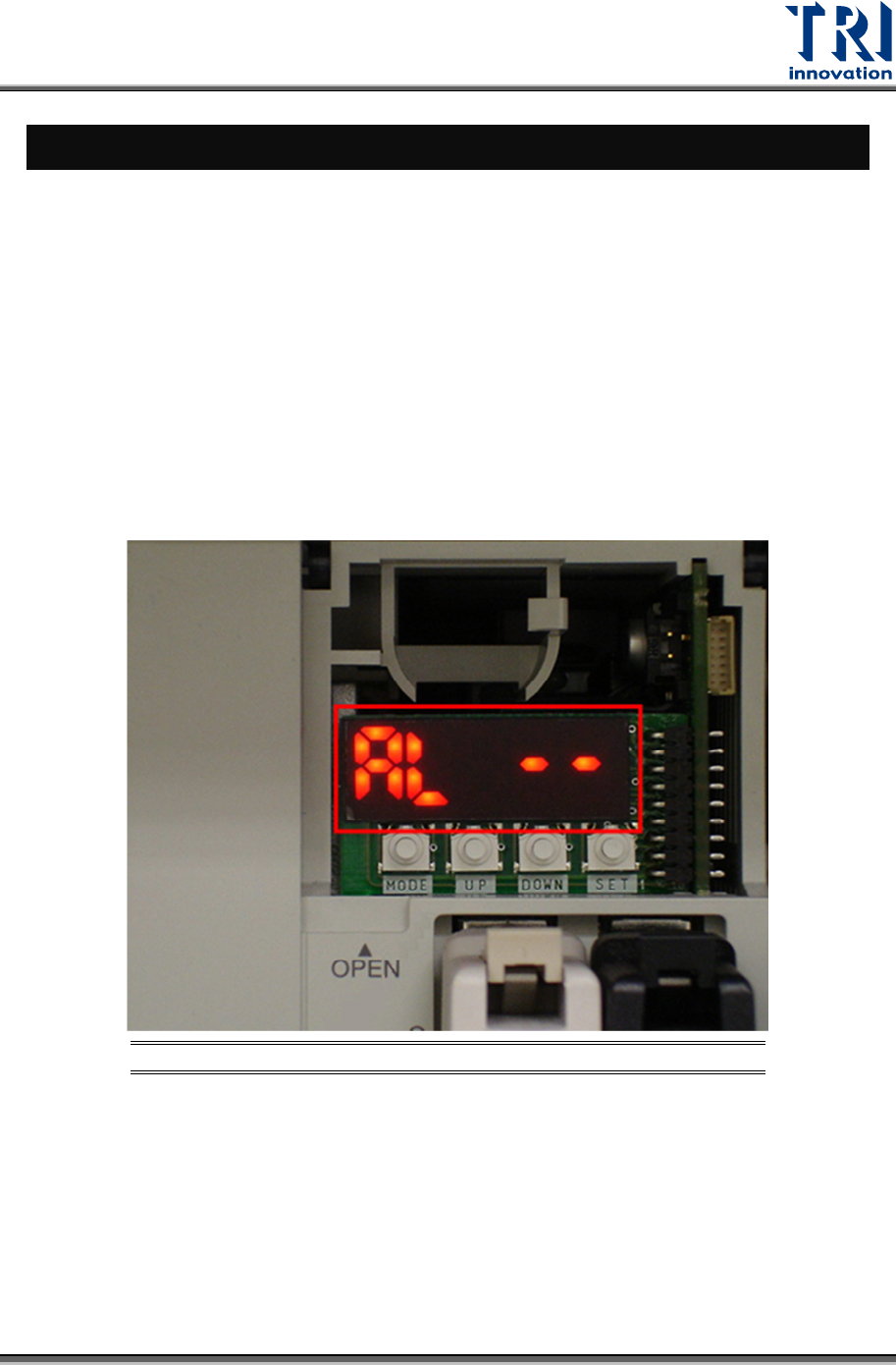
ERROR CODE
Open the cover up and check the error code. (In normal situation it shows [AL --]).
Figure 33: MR-J2 LED Displays Alarm Codes
If it does not display the [AL --] screen, press [MODE] button to exchange the display.