TR7600 SIII_Hardware_en_v_2_0_4 - 第56页
Test Research, Inc . 46 TR7600 SIII Series Us er Guide – Ha rdware 6.3 DSP M odule Signal Lighting Figure 37: DSP Modul e Signal Light ing PEL: Positive Li m it Sensor M EL: Negative Limit Sensor ORG: Original Sen …
Test Research, Inc.
TR7600 SIII Series User Guide – Hardware 45
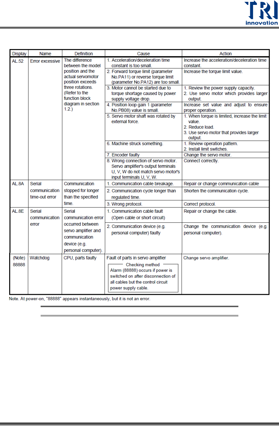
Table 4: Error Codes of Movement along Y, Z, V and W Axes
Test Research, Inc.
46 TR7600 SIII Series User Guide – Hardware
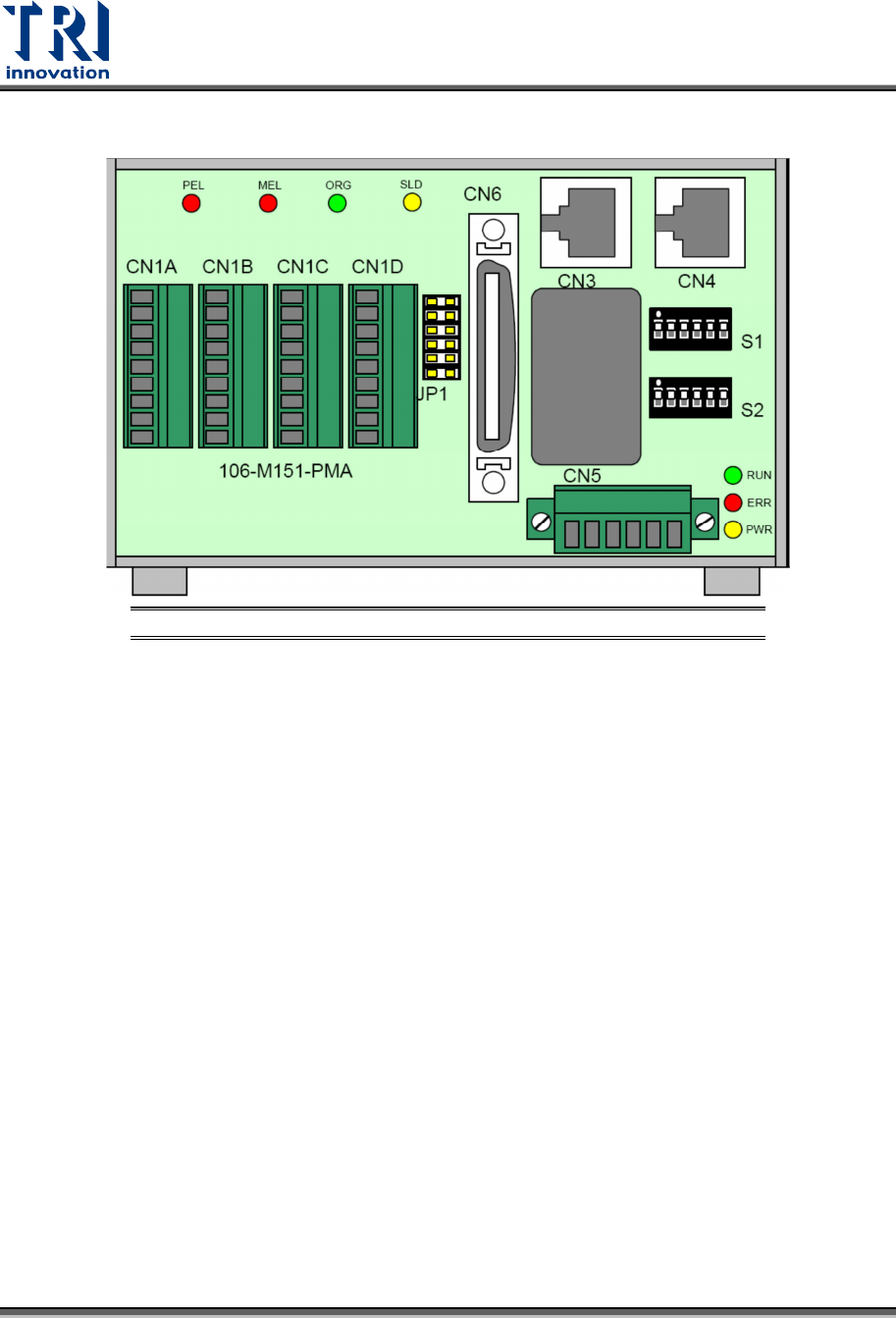
6.3 DSP Module Signal Lighting
Figure 37: DSP Module Signal Lighting
PEL: Positive Limit Sensor
MEL: Negative Limit Sensor
ORG: Original Sensor (Disabled here)
SLD: Deceleration Sensor (Disabled here)
RUN: RUN
ERR: ERROR
PWR: POWER
Test Research, Inc.
TR7600 SIII Series User Guide – Hardware 47
6.3.1 DSP
S
LAVE
M
ODULE
R
EPLACEMENT
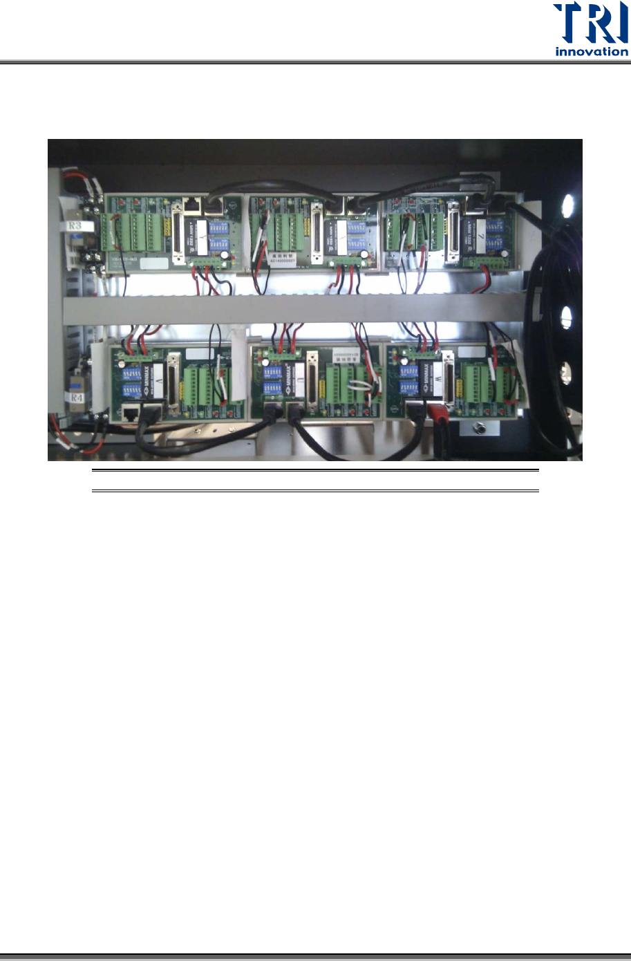
There are six DSP Slave Modules for each X, Y, Z, U, V, and W axes.
Figure 38: DSP Slave Module Replacement – Position
Replacement Steps
1) Turn off the power.
2) Remove the broken module; refer to the wiring diagram for the cable connection.