TR7600 SIII_Hardware_en_v_2_0_4 - 第61页
Test Research, Inc. TR7600 SIII Series User Gu ide – Hardwa re 51 Control the front conveyor Turn the upper knob clockwise to d ecrease f ront c onvey or pulling speed or turn the k nob counterclockwise to increase pul…
Test Research, Inc.
50 TR7600 SIII Series User Guide – Hardware
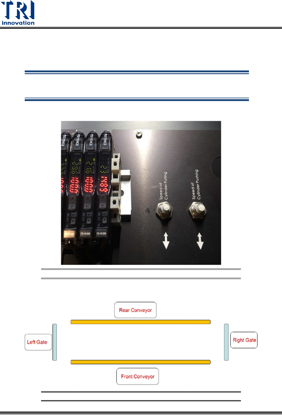
6.5 Conveyor Control
Two knobs installed next to the FFC Calibration Board are used for the pulling & pushing
control.
NOTE: Please don't change the conveyor pulling and pushing speed
without TRI engineers' permission. Changing the speed arbitrarily may
cause problems hard to solve.
Figure 41: Pulling and Pushing Control
Figure 42: Rear and Front Conveyor
Test Research, Inc.
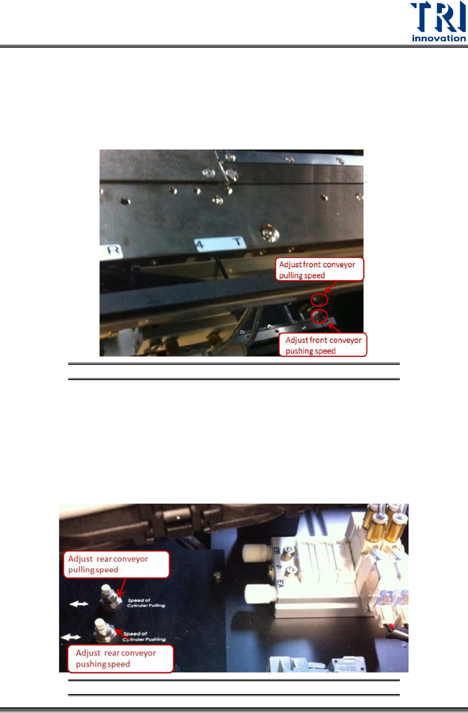
TR7600 SIII Series User Guide – Hardware 51
Control the front conveyor
Turn the upper knob clockwise to decrease front conveyor pulling speed or turn the knob
counterclockwise to increase pulling speed.
Turn the lower knob clockwise to decrease front conveyor pushing speed or turn the knob
counterclockwise to increase pushing speed.
Figure 43: Front Conveyor Control
Control the rear conveyor
Turn the right knob clockwise to decrease rear conveyor pulling speed or turn the knob
counterclockwise to increase pulling speed.
Turn the left knob clockwise to decrease rear conveyor pushing speed or turn the knob
counterclockwise to increase pushing speed.
Figure 44: Rear Conveyor Control
Test Research, Inc.
52 TR7600 SIII Series User Guide – Hardware
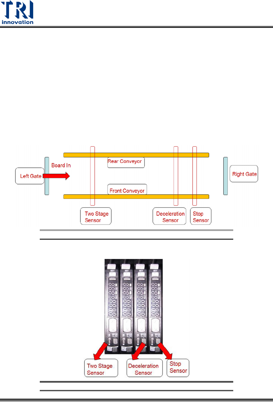
6.6 Digital Fiber Sensor
There are three sensors related to conveyor movement.
1) Stop Sensor: The inspected board will stop at where Stop Sensor is.
2) Deceleration Sensor: The inspected board starts to decrease its speed once it passes
the deceleration sensor.
3) Two-Stage Sensor: This sensor is used when two-stage function is activated.
The sensors will work differently according to Left-In or Right-in board direction.
a) Case 1: Left-In board condition
Figure 45: Sensor Arrangement for Left-In Board
Figure 46: Sensors for Left-In Board