00196845-02_AI_Vakuumpumpe_SXDX4_X-Serie-S_de_en - 第105页
Fitting the Vacuum Pump 3.2.16 Checking the Direction of Pump and Fan Operation Changeover Vacuum Pump Vakuumpumpe 105 ► Fit the filter bac k into place. ► Close the installation locat ion wi th the cooling plate (se e &…
Fitting the Vacuum Pump
Changeover 3.2.16 Checking the Direction of Pump and Fan Operation
104 Vacuum Pump Vakuumpumpe
3.2.16
3.2.16 Checking the Direction of Pump and Fan Operation
Checking the Direction of Pump and Fan Operation
3.2.16.1
3.2.16.1 Checking the Direction of Pump Operation
Checking the Direction of Pump Operation
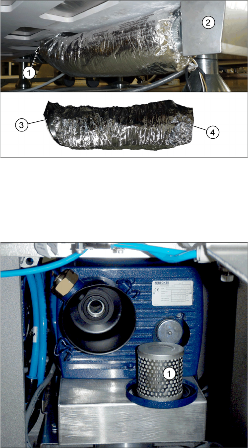
Aluminum flex-tube installation
1. Vacuum pump
2. Air box
3. Tube end with flange, pre-assembled with hose
clamp – to the vacuum pump
4. Tube end without flange – to the air box
► Fix the tube end with flange at the air outlet conduit of
the vacuum pump from below.
► Fix the tube end without flange at the air box with a
hose clamp.
► Loosen the brackets holding the filter cover and re-
move the filter (1).
Fitting the Vacuum Pump
3.2.16 Checking the Direction of Pump and Fan Operation Changeover
Vacuum Pump Vakuumpumpe 105
► Fit the filter back into place.
► Close the installation location with the cooling plate (see "3.2.17 Fitting the Cooling Plate with Fan"
[ ➙ 106]).
► Check the connections for air-tightness. Make sure that they are not sucking in air incorrectly.
3.2.16.2
3.2.16.2 Check the Direction of Fan Operation
Check the Direction of Fan Operation
► Switch the placement machine on at the main switch. The vacuum pump must also switch itself on,
although this might not occur immediately after the machine is switched on.
► Start the vacuum pump (see "3.2.16.1 Checking the Direction of Pump Operation" [ ➙ 104]).
► Check the direction of fan operation. The fan must blow air into the machine.
If the fan is running incorrectly, turn the 24 Volt in the Mini Mad BN Lock connection.
► Switch the machine on at the main switch. The vacu-
um pump must also switch itself on, although this
might not occur immediately after the machine is
switched on.
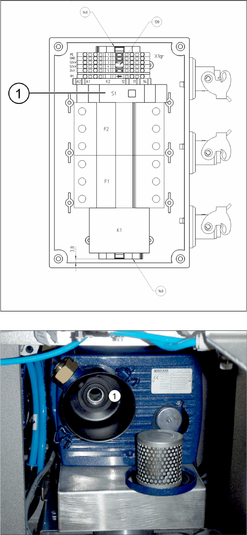
► Start the vacuum pump with the S1 button (1) on the
connection unit. The button can be reached through
an opening in the housing.
► Hold a hand or sheet of paper in front of the opening
of the pump through which air is sucked in (1).
⇨ The pump must be sucking air in!
► If the pump is running in the wrong direction, discon-
nect the entire system from the voltage supply. Un-
plug the vacuum pump from the power.
► If both connections for the vacuum pump show the
same effect, rewire the network cable connection in
the connection unit (exchange the phases).
► If only one vacuum pump is running incorrectly, re-
wire at the relevant fuse (exchange the phases).
F1: Pump 1
F2: Pump 2
Fitting the Vacuum Pump
Changeover 3.2.17 Fitting the Cooling Plate with Fan
106 Vacuum Pump Vakuumpumpe
3.2.17
3.2.17 Fitting the Cooling Plate with Fan
Fitting the Cooling Plate with Fan
3.2.18
3.2.18 Fitting the Connection Unit
Fitting the Connection Unit
NOTICE
Checking the direction of pump operation
Check the direction of pump operation before you close the installation location with the cooling
plate (see "3.2.16.1 Checking the Direction of Pump Operation" [ ➙ 104]).
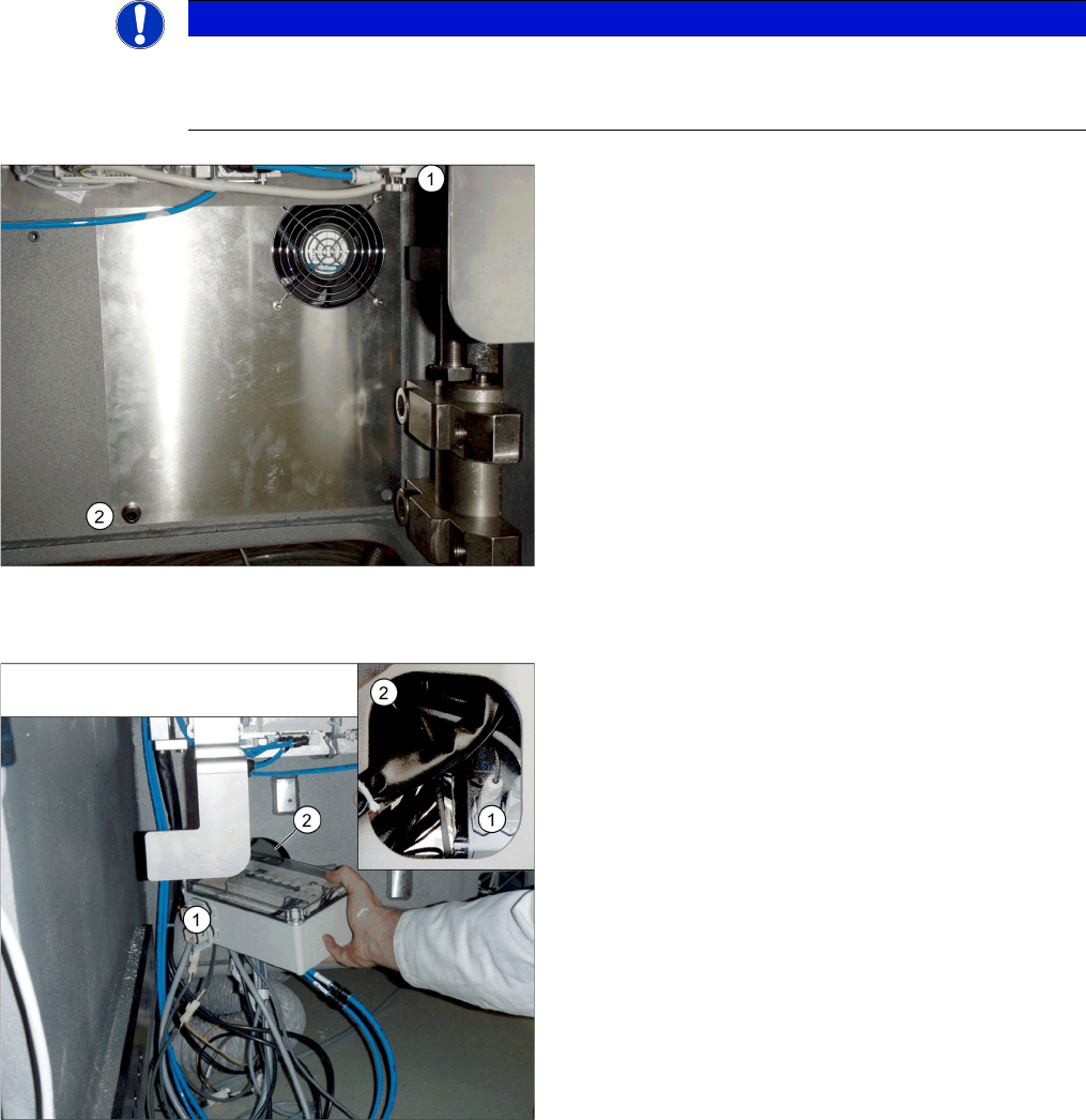
► Connect the fan cable to the "connection unit assem-
bly" (see also "3.2.9 Running the Supply Cable"
[➙98]).
► Position the top fixture hole on the cooling plate onto
the M10 screw previously inserted (1) and secure this
with a washer and nut.
► Secure the cooling plate with an M4 screw (2), insert-
ed from the front.
► Perform a fan function test (see "3.2.16.2 Check the
Direction of Fan Operation" [ ➙ 105]).
➢ If the direction of running is correct for both the pump
and fan, you can fit the "connection unit assembly"
into its installation point in the machine base.
► Unplug all connections from the connection unit (1).
► Slightly turn the connection unit to fit it through the
opening in the machine base (2).
► Restore all connections.